SIDI version 1.2
Description of the hardware
Because the old SIDI v1.1 was based on the DOS operating system and parallel port interface, it was plagued by several deficiencies:
- sample timing based on software loops (VLBI not possible)
- limited memory
- new computers have no LPT port
- limited sampling rate (bandwidth)
Therefore, it was necessary to switch both the OS and the interface.
SIDI 1.2 runs on LINUX and uses the USB 2.0 interface to something more
up to date.
USB sampler
I have developed a simple sampler, based on my
UUUSB board,
which is an USB 2.0 interface based on the Cypress CY7C68013 chip.
Alternatively, one might use an USB 2.0 interface extracted from some
cheap USB gadget, like the
TRUST Spacecam 380,
which contains a very nice USB 2.0 interface.
NOTE: it must be an USB 2.0 high speed device,
USB 1.x full speed or even USB-HID are useless for SIDI purposes.
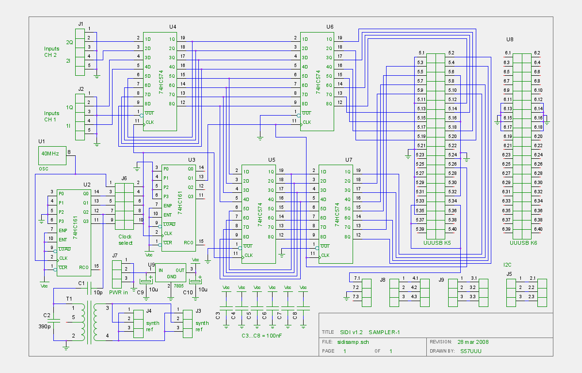
The sampler consists of four serial to parallell converters, that
enable a better utilization of the CY7C68013's bandwidth.
The sampler also contains the 40MHz master oscillator with dividers, to
provide both the sampling clock and the 5MHz tuner references. Sample rates
of 40,20,10,5 and 2.5 MHz can be selected by jumpers.
The sampler itself is just a bunch of shift registers an buffers, all
implemented with the 74HC574 chips.
T1 is a standard 10.7MHz IF transformer with added capacitance (C2), to bring
it down to 5MHz. Select C1 to get cca 0.5Vpp on J3 and J4 (check your
tuner's requirement).
Everything (sampling clock and synthesizer references) is derived from the
same 40MHz oscillator. In a locked system, this is the oscillator that would
have to be locked.
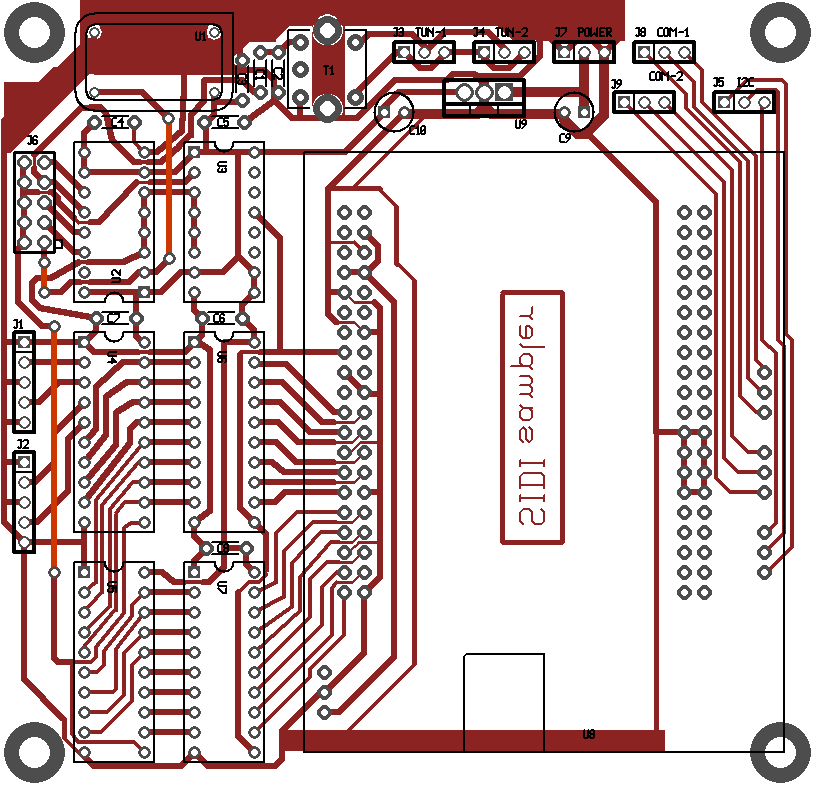
The layout has sockets for the piggyback fitting of the
UUUSB board,
It is
designed as a two layer board, but there are only three straight links on the top side,
therefore it can also be made as a single layer board with three wire links.
This makes it suitable for home production, using toner transfer or similar
techniques.
Links to the
design files
are at the bottom of this page.
Modified TBA120S IF strip
Soon after firing up the new sampler, I found out that the LM319 is rather
slow for the 20MHz sample rate.
 To improve this, I replaced it with a simple discrete transistor level shifter:
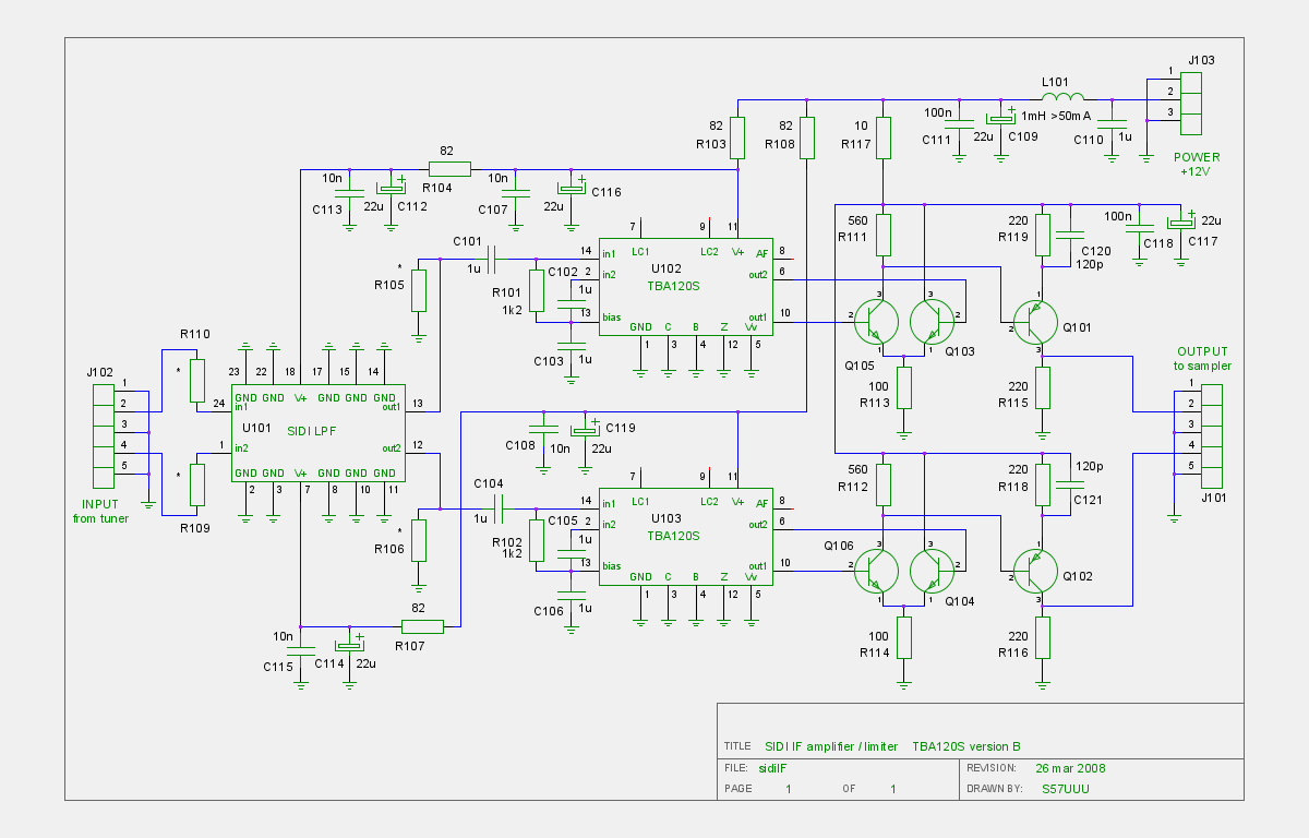
The transistors are 2N2222 and 2N2907.
R109 and R110 are there to match the filter. The tuner's outputs have quite
low impedance, so with the filters designed for 1k, these two resistors
should be 1k.
R105 and R106 match the output of the filter. With filters designed for 1k,
they are not needed, as R102 and R102 already provide adequate matching.
The transistors are running at a rather high current, so they get hot.
Install R104, R107, C112, C113, C114 and C115 only if you intend to
use active filters.
Otherwise it is better to leave them out, to minimize possible feedback.
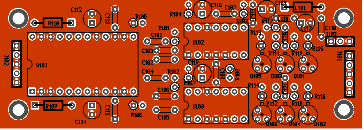
The board is double sided, the component layer is a full size ground plane.
You can make it with a single (solder side) film, by covering the whole
top side with adhesive foil. After etching, use a drill to clear the copper
around the non-ground holes.
Links to the
design files
are at the bottom of this page.
New MC10116 based IF strip
While TBA120S are still plentiful on Ebay, decided to make an IF strip based on something that the distributors still carry. First I made an IF strip based solely on discrete transistors, but later decided to use the MC10116 ECL line receivers. Admittedly, these are of about the same vintage as TBA120, but distributors still carry them (Farnell 1468722, digikey MC10H116FNGOS-ND,
RS components 787-6857).
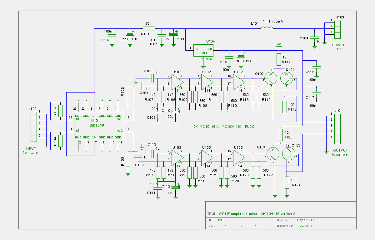
The transistors are 2N2907.
R109 and R110 are there to match the filter. The tuner's outputs have quite
low impedance, so with the filters designed for 1k, these two resistors
should be 1k.
R105 and R106 match the output of the filter. With filters designed for 1k,
they are not needed, as R106 and R116 already provide adequate matching.
Install R101, C106 and C107 only if you intend to use active filters.
Otherwise it is better to leave them out, to minimize possible feedback.
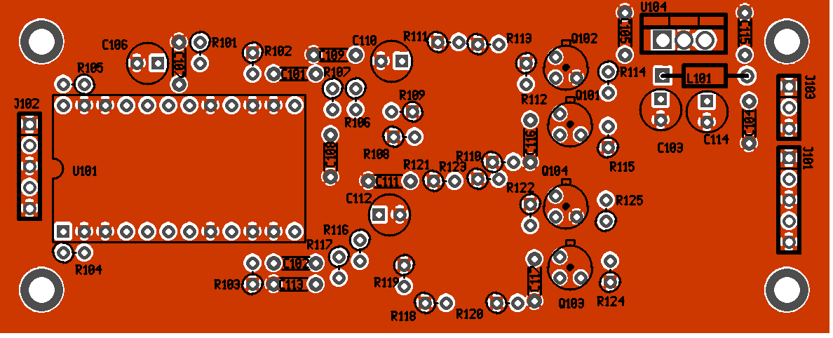
The two MC10116 chips (SMD) are soldered on the bottom (solder) side.
The board is double sided, the component layer is a full size ground plane.
You can make it with a single (solder side) film, by covering the whole
top side with adhesive foil. After etching, use a drill to clear the copper
around the non-ground holes.
Links to the
design files
are at the bottom of this page.
IF filters for higher bandwidths
The filters are of the same topology as in SIDI v1.1, built on the same type
IC socket, so they are mechanically interchangeable.
The values approximate a Chebyshev 0.1dB response at an impedance of 1k.
22pF, 27uH, 39pF, 27uH, 22pF make a 8MHz lowpass
47pF, 56uH, 82pF, 56uH, 47pF make a 4MHz lowpass
100pF, 120uH, 180pF, 120uH, 100pF make a 2MHz lowpass
180pF, 220uH, 330pF, 220uH, 180pF make a 1MHz lowpass
End of march 2014, we setup SIDI 1.2 at Pavle's place with two 3m dishes
on a 44m baseline, to try for the first fringes. After some tweaking, the results were very encouraging. NOTE: in the picture below, the fringes have been slowed down in the viewing software.
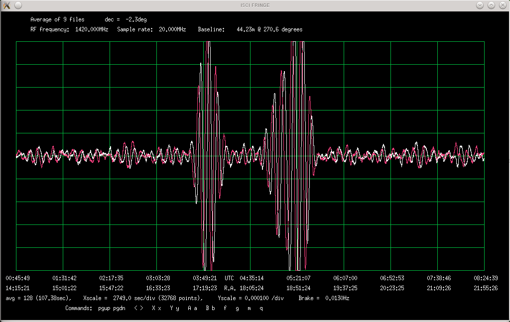
As can be seen in the attached picture, there is almost no place left, where one can see 'pure noise', there are fringes virtually everywhere. This picture is an average of nine scans, to make things smoother, but most of the fringes can be seen in a single scan too.
What this means is, that most of the time, there is at least one detectable source in the antenna beamwidth, and often there is more than one, so we have reached the 'confusion limit'.
The bigger set of fringes on the left are the sources NVSS 172025-005832 and 172034-005844 (20 and 31 Jy), about a degree offbeam, and the right set of big fringes is a mashup of a dozen or so sources, beginning with NVSS 184124-015255 and 184124-015246 (cca 3 Jy each) and then the group around NVSS 184736-015522 (11Jy). NVSS = the 1.4GHz NRAO VLA Sky Survey, Condon+ 1998.
Pavle S57RA has put some photos of the setup at his homepage here:
S57RA homepage (external link)
For pictures, see under "Gallery" and for more results look under "Radio sources recorded with SIDI". I plan to release soon the fringe viewing
software, that can be used to read the recorded files.
Sky at minus ten degrees
When not otherwise specified, all of the design files are for the GEDA tools.
I am using some special symbols and footprints, so before you can use the
schematic and layout files, you need to download the following two files:
gschem symbols
PCB footprints
After extracting, put the path to the symbols directory into
~/.gEDA/gafrc like this:
(component-library-search " path to 0mc-sym")
so that gschem can find the symbols.
For PCB, you need to put the path to pcb-elements into ~/.pcb/settings,
like this:
lib-newlib = path to pcb-elements
Sampler schematic
Sampler layout
TBA120 IF schematic
TBA120 IF layout
MC10116 IF schematic
MC10116 IF layout
Up to main SIDI page
Copyright info