SIDI version 1.1
Description of the hardware and software
Soon after the first experiments with SIDI 1.0 I started work on a new version,
motivated mainly by three reasons:
1. SIDI 1.0 lacked any frequency agility, often needed to avoid QRM
2. To build one, you had to assemble some microwave circuitry, which I think
most people would prefer to avoid.
3. The S53MV IF amplifier was unnecessarily complicated for this type of receiver.
As mentioned before, the idea was to use tuners from digital SAT-TV receivers
and simple limiting IF amplifiers with RC filters, like this:

The comparators (one bit A/D) are now included on the IF boards.
Building this requires ALMOST no RF skills - no need to assemble any microwave circuits.
However, it is stil a high-gain high-sensitivity circuit that can be prone to self
oscillation and interferrence pickup, so I would not recommend it as a project for someone
with absolutely no experience with building electronic circuits.
Tuners
The main concern in the beginning was if the tuner's synthesizers would be coherent
enough. The tuner chips have relatively good phase noise specifications (about -75...-80
dBC/Hz at 10kHz offset). The first tests I have done have shown acceptable results, so I
proceeded with the development of tuner based SIDI.
I've used the tuners from "sky star 2" PC boards. These do need some minor modifications,
but luckily not in the RF circuits - see
Tuner harvesting and modification
I have also developed an
400...450 MHz frontend for SIDI
IF strips
The IF strips are based on the TBA120S chips (limiting FM IF amplifiers/demodulators).
These are ancient chips, actually among the first to be used widely in TV sets, but
are still easily available. (The dealers are starting to charge "collectors item prices"
on them, so this might force me to think about alternatives :-)
I've used them because they are highly symmetric, with differential outputs, so
they can directly drive the comparators, and typically achieve less than 1% of DC
offset without any adjustment. (drifting DC offsets were a big plague on SIDI v1.0)
The complete schematic looks like this:
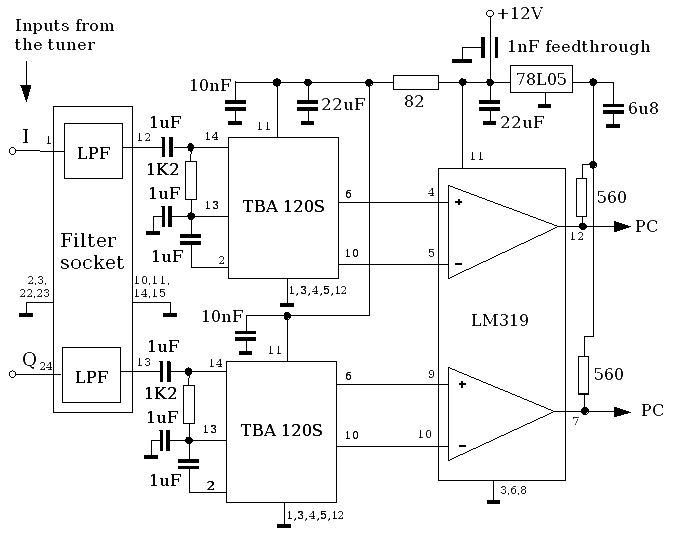
It could hardly be simpler!
The 1uF capacitors are of non-polarized (ceramic) type, 6u8 and 22uF are electrolytics.
The lowpass filters are built on 24 pin IC sockets, so they can easily be changed
to suit various sampling rates and QRM situations.
The only thing that could be a bit of a problem is that the DC bias on the TBA120S outputs
is just barely within the common mode input range of the LM319 when run without negative
supply. I purposedly avoided a negative supply to keep everything portable with a single
+12V supply. So far I have not encountered problems because of this, but chips from different
manufacturers could have different DC bias and/or common mode range and potentially cause
problems.
If you have a suitable negative voltage (-5...-12V) available from a mains operated
supply, you can use it and slep better :-)
(I want to avoid switching voltage converters because they have working
frequencies within our baseband range!)
MAYBE one day I will make real PCB designs for this, but for now
the IF strips are built on 35x100mm pieces of "hole matrix" protoboard.
NOTE:
Only the type that has a solid copper plane on the component side is suitable!!
For additional shielding, a 30mm wide ribbon of 0.5 - 1mm thick brass is soldered
around the rim of the boards.
Two IF strips, one with filter inserted (the old active RC filter version that I later abandoned)
and the other one without filter, look like this:

First I wanted to use active RC lowpass filters to avoid coils that can pick up
magnetic interference from switching supplies in computers, CRT monitors etc.
But later I decided to stay with passive LC filters because of ther simplicity
(less components, no supply requred etc).
A 200kHz 5th order 0.1dB ripple Chebyshev lowpass for 1kOhm impedance with the components
rounded to the nearest standard values looks like this:

It is built on a 24pin IC socket so that various filters can be easily replaced. (Both I and Q
filters are built on the same socket, the pin numbers in parentheses are for the Q channel)
I have used a LC meter to select components within 1% of the nominal value, to keep
the filters well matched. To test channel matching, I
connected the same noise (from a single tuner output) to all
four inputs and got better than 99% correlation! (97% before Van Vleck)
The 5th order LC filter looks like this:

The old RC active filter (3rd order only!) looked like this:

Later I abandoned this filter. It needs power supplied around the high gain TBA 120,
reuiring very good decoupling. Since my intention is to make SIDI easy to build, I rather
avoided this potential source of self oscillation.
Another reason is that with an LC filter you can make a higher order filter using
fewer components.
Master oscillator (TCXO)
The original reference frequency of the tuners was 4MHz. I am using an old 5MHz TCXO from
a surplus military SSB radio. A 10MHz version and a divider by two would also work.
For future experiments with locking for VLBI, it is desirable that the TCXO has an fine tuning
voltage input, and a frequency of 5 or 10MHz, compatible with most standards (GPS, rubidium).
I2C interface
This is a simple two transistor circuit:

In the next version (SIDI 1.2, USB based) this will probably not be needed any more,
because most USB interface chips have a built-in I2C interface.
Putting it all together
All the components described above are then put together according to this schematic:

If you use a different type of tuner, the pin numbers on the tuners will be
different, of course.
The tunning voltage inputs of the tuners (pins 7) are connected to 12V, which will
cover most of the interesting frequencies. If you have 30V handy (in an mains operated
setup - I do not recommend switcing converters) you can use them here for full frequency
coverage, 950...2150 MHz.
The "Vlna" inputs (pins 1 on the tuners) supply DC to the center conductor of the RF input connectors,
intended for preamplifier (LNA) power supply. Connect a DC voltage corresponding to
what your LNA needs.
For example, for the S53MV preamps, I simply use 12V, and for the Pavle's GPS antennas
used in the
imaging experiment,
which need 3V, I simply connected them to 5V thru a couple of series diodes to reduce the
voltage to cca 3.5V.
If your LNA has a separate supply terminal (is not supplied thru the coax)
you can leave these pins unconnected.
The whole SIDI 1.1 hardware then looks like this:

Top left is the 5MHz TCXO used to feed the reference inputs of both tuner's synthesizers,
top right the I2C interface and 5V stabilizer.
Below are the tuners and IF strips.
The connector top left is for the (future, not yet implemented) locking of the TCXO.
On the right are the 12V supply connector and the 25 pin parallel port connectors.
The aluminium chassis provides a solid ground for all of the components.
Parts list
The following is a list of parts needed to make a basic two channel
SIDI 1.1 interferometer, as pictured above.
quantity	item

2		direct conversion digital satellite tuner
1		TCXO, 5 or 10 MHz with electric tuning capability
1		2-pin power connector
1		25 pin sub-D female connector
2		35x100mm hole-matrix protoboard with copper plane (*)
1		30x30mm protoboard
1		cca 0.6m RG-188 or similar thin coax cable
1		cca 0.6m x 30mm brass ribbon, 0.5 - 1mm thick (or 2 suitable metal boxes)
1		170 x 300 x 1.5mm aluminium sheet
1		cca 2m insulated wire (thin, non-litz)

4		24pin IC socket (deluxe version with round sockets)

1		7805  voltage regulator
2		78L05  voltage regulator
4		TBA120S   FM IF chip
2		LM319   dual comparator chip
2		2N2222 or similar transistor

1		10 ohm 0.25W 5% resistor
1		18 ohm 0.25W 5% resistor
2		82 ohm 0.25W 5% resistor
4		560 ohm 0.25W 5% resistor
4		1K2  0.25W 5% resistor
4		3K3  0.25W 5% resistor

2		1nF feedthrough capacitor
4		1nF 1% (selected) capacitor
2		1.5nF 1% (selected) capacitor
4		10nF ceramic capacitor
12		1uF NON-electrolytic capacitor
2		4u7 16V electrolytic capacitor
2		6u8 16V electrolytic capacitor
4		22uF 16V electrolytic capacitor
1		1000u 16V electrolytic capacitor

4		1mH 1% (selected) inductor
To complete the observing station, you need to add:
- two antennas with preamplifiers and cables
- a 12 V power supply (or battery)
- an IBM PC compatible computer
- an 25pin male to 25pin male parallel cable
Power supply
SIDI 1.1 runs from a single +12V supply, to make it portable in combination with a laptop PC.
I think portability is important for an amateur VLBI device, since few amateurs will be able to
afford several fixed installations needed for good UV plane coverage.
Limiting oneself to +12V brings some drawbacks, like no negative supply for the comparator
and less than full frequency coverage of the tuners.
Today matchbox sized voltage converters are available to convert from 12V or whatever
to quasi any other voltage. I could have used these to get -12V and +30V, but preferred
to avoid them, because their switching frequencies fall into the SIDI baseband where we
have very much gain.
For the same reason, if you run SIDI from the mains, I suggest a supply based on a mains-frequency
transformer and big capacitors, not a switchmode thing like from old PCs.
Surely, with good decoupling and filtering voltage converters could be used succesfully,
but I want SIDI to be easy to build. Sleuthing out EMC problems and removing them can
be a very daunting task, so it is better to avoid them by designing potential sources out.
EMC problems of this kind can manifest themselves in very obscure and confusing ways!
Of course, I am not saying you should not try and use converters if you want.
I welcome any effort to improve on the above design, especially if you share your
results with the rest of us.
Software
Up to main SIDI page
Up to S57UUU Astronomy Page
Copyright info