SIDI, the SImple Digital Interferometer
Introduction and FAQ
Contents:
Background
Design goals
Design guidelines
Basic design choices
Incarnations of SIDI (+links to detailed descriptions)
-- Version 1.0
-- Version 1.1
-- Version 1.2
SIDI debugging guide
FAQ
For a condensed introduction to SIDI version 1.1 (now obsolete), see my
presentation from the
2006 ERAC Congress
A more recent overview article has been published here:
BAA RAG RAGAZINE aug 2014 (EXTERNAL LINK)
Some results are here:
Sky at -10 degrees
Background:
The ERAC (European Radio Astronomy Club) has a project to build
an amateur VLBI system called ALLBIN. While several amateur radio
astronomers have done classic (non-VLBI) interferometry before,
they all did it using analog techniques, see for example:
Hans Michlmayr's phase
switched interferometer (EXTERNAL LINK)
IRO interferometer (EXTERNAL LINK)
However, VLBI requires many operations like correlation search and
delay equalization, fringe stopping, etc... that are very hard to
do with analog circuits.
Therefore I decided to try designing a digital interferometer as
one of the first steps toward the ALLBIN project. In the 21st
century it is probably not necessary to explain the advantages
of going digital, but let me mention only one:
it allows things to be done in software. It is much easier for
amateurs to develop software than hardware, since it requires much
less of a material basis, like instrumentation etc.
My goal is to publish here all the gory details needed to reproduce various
versions of SIDI - with all schematics, software sources etc - so anybody
can build and use it.
Usually I announce any new developments of SIDI at the
ERAC-VLBI Yahoo group (EXTERNAL LINK)
Design goals:
To design a digital radio interferometer for radio astronomy
accessible to amateurs, suitable for both connected and
disconnected (VLBI) interferometry.
Design guidelines:
Design guideline #1:
Keep everything as simple and cheap as possible,
so that as many amateurs as possible can build it, while also keeping
it flexible and open for future improvements.
Design guideline #2:
The design should be modular, so that many
different interferometers can be built from the standard modules
and upgrades and changes can be made one module at a time.
Design guideline #3:
Avoid the use of exotic hardware and software
components that are hard to get or prone to obsolescence. The design
should be fully open, no proprietary IP etc.
In short, KISS (Keep It Simple, Stupid!) - but NOT
at the expense of performance. Within a given bandwidth/bitrate, SIDI will measure
up well with anything that can be built using arbitrarily complex and expensive
high-tech!
My moto is: do not use more technology than really needed, and
use the lowest technology that will do the job well.
Do not use a bulldozer to plant a single daisy.
Example: when NASA wanted their astronauts to take some notes, they
realized that normal ballpoint pens don't write in zero G. So they
spent $$$$$ to develop a zero-G ballpoint pen.
The Russians simply gave their cosmonauts normal pencils.
Searching the web, one can find traces of failed amateur experiments
with digital radio interferometry.
I think the main reason they failed was that the guys were thinkig something like:
"Wow! I've got this turbo charged zillion gate FPGA and the super-optimizing
artificially intelligent VHDL compiler! Let's try to do some interferometry!"
instead of:
"What is the simplest working digital interferometer that I can build?"
But please note that I do put much emphasis into designing SIDI so that it is
fully open for future enhancements of any complexity.
I just want to take a step by step approach, first building something
simple, getting it to work and use it to gather experience. After that,
improvements can be added gradually and in a modular fashion.
Do not try to conquer a mountain in a single hop - you're guaranted to fail!
Basic design choices:
Two basic choices were made for SIDI, mainly to comply with the design
guideline #1: direct conversion receivers and one bit sampling.
In an interferometer where correlation is done after frequency
conversions, all local oscillators must be coherent. In VLBI, this
can only be achieved by phase locking the LO's. Phase locking is
a tricky business, so it is advisable to reduce it to a minimum in
an amateur setup. That is one reason for choosing a direct conversion
receiver, which only has a single LO. Another is that it is one of the
simplest receivers to build and tune up.
In the past, direct conversion receivers were considered inferior toys,
but with the advent of DSP their shortcomings have dwindled and they are
becoming more and more popular.
Many modern radio systems (like cellular) use them almost exclusively.
Radio astronomy signals are usually well below the receiver noise,
so sampling them with high precision makes no sense, since most of
the bits will only contain receiver noise. Using single (yes, ONE)
bit sampling looses only cca 2dB in this case, of which one can be
reclaimed by oversampling. Bandwidth is much more important for
sensitivity here than number of bits, and single bit sampling makes
very fast circuitry qiute simple. Single bit sampling brings so much
simplification (like no AGC etc) at so little cost that I think it
is the only sensible choice for an amateur interferometer at this point.
Many professional VLBI systems have used 1-bit sampling, and most of
them use only two bits.
Most GPS receivers also use 1-bit techniques, and another
very famous project
using single bit samples is the Seti@Home distributed computing project.
See also FAQ #10 below.
Incarnations of SIDI
SIDI version 1.0 (It's alive!!!!!!!!)
This was the first working version, with which I got the first
amateur digital radio fringes ever.
For this version of SIDI, I used modules from Matjaz S53MV's 23cm
megabit PSK packet radio transceivers, because they were lying
around in my drawers. The data goes into the PC via
the parallel port, using software sample timing. Software runs under
DOS / Borland C 3.0.
This was meant mostly as a proof-of-concept prototype, and I probably won't
do any improvement work on it in the future. Therefore I do not recommend
it for construction.
For a description of hardware, software and the results obtained, click here:
SIDI 1.0
SIDI version 1.1
This is the first version that
uses tuners from digital satellite TV receivers and simplified
IF amplifiers.
It still uses the LPT port and DOS software.
Its main advantages compared to v 1.0 are frequency agility and much
easier construction - no microwave skills required.
For a description of the hardware and software, click here:
SIDI 1.1
For the first results with it click here:
first fringes with SIDI 1.1
An experiment with synthesized interferometric images
is described here:
Imaging with SIDI 1.1
I have also developed an
400...450 MHz frontend for SIDI
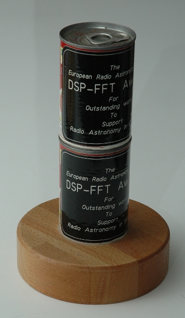
I presented SIDI v1.1 at the 2006 ERAC congress, and it won a special
double-decker version of the ERAC FFT-DSP award.

At least two other people have successfully built their versions of
SIDI v1.1:
Kimmo Lehtinen from Finland (EXTERNAL LINK)
and
Alexander Plaha from Ukraine 1. (EXTERNAL LINK),
Alexander Plaha from Ukraine 2. (EXTERNAL LINK),
who added an USB interface and ported the software to Windows.
I do not plan further development work on this version.
SIDI version 1.2
This version is the current version of SIDI..
The main difference compared to v 1.1 is a USB 2 interface and migration
to GNU/LINUX.
With a couple of 3m dishes, it can detect single digit Jansky sources in one
drift scan pass. Averaging a few scans, it reaches the confusion limit, when
most of the time, there is more than one detectable source within the antenna
beamwidth.
For a description of the hardware, and software, click here:
SIDI 1.2
Some results obtained with SIDI 1.2 are here:
Sky at -10 degrees
Other results of the observation with SIDI 1.2 are on the webpage of
Pavle S57RA (EXTERNAL LINK), including some
photos of the setup (EXTERNAL LINK).
SIDI debugging guide
I have also written some instructions about getting SIDI to work, in a step-by-step manner. Here they are:
SIDI debugging guide
FAQ:
I've just published this, and people haven't yet asked many
questions, so this is mostly a list of "Fearlessly Anticipated Questions"!
Q1: Why not use the (Icom, Yaesu, Kenwood....) commercial
general purpose communication receiver?
A1: There are two main reasons for this: 1. you cannot phase lock their
many internal oscillators 2. their bandwidth is too small for
serious work. Currently there is no way around building your own
receivers. Because of modularity, it could become possible to use
slightly adapted modules from surplus cellular, satellite and similar
equipment.
In the meantime, somebody notified me of the fact that some new model
has a master clock reference input and an wideband IF output.
Well, that MAYBE solves the locking problem, (is it possible to know
the exact division ratios used in the internal synthesizers? Are the multiple
PLL loops and conversions used in these complicated receivers coherent enough?)
but the bandwidth question remains.
In the future I would like to use 10 and more MHz of bandwidth,
which a 10.7 MHz IF output certainly does not have.
Unless direct sampling would be used (precluding the "step by step" approach),
to convert that 10.7MHz output to I and Q would require
another locked oscillator and mixers that you would still have to provide...
That is not much less hardware than a microwave direct conversion RX!
And of course, these stupid big boxes with all their bells and whistles
and the QRM their CPUs produce would be a nightmare to use...
For an interferometer you need at least two of them - so their price
is even less attractive!
Q2: Why didn't you use a sound card as input device?
A2: The reasons are almost identical as above: 1. you have no control
over the sampling clock 2. their bandwidth is too small. There
probably are some high-end sound cards that allow external smapling
clocks, but these aren't cheap and easily available, so the design
guidelines rule them out. And they will NEVER have the bandwidths
I plan for the future versions of SIDI.
External clocking is essential for VLBI work
where the data must be coherently sampled and recorded
on separate computers.
Q3: Why do you use the printer port?
A3: Mainly to comply with design guideline #1 above. The LPT port
offers cca a MHz of bandwidth with only very simple dumb hardware.
New standards like USB, IEEE1394, SCSI etc all require intelligent
hardware that can identify itself, negotiate bus bandwidth etc.
There are some interface chips available that will do most of those
chores, but using them would go against design guideline #3 above -
the standards in the PC world change so quickly that a design
published using chips available today would be useles in a few years.
However because bandwidth is so important it would also be stupid
to limit oneself in this respect, so I DO plan switching to a more
powerful way of getting bits into the computer, probably using
FPGA's and open IP.
But since getting bits into the PC faster and under external clock
is so important, I still do think
about USB 2.0 - currently I'm looking into Cypress FX2 chips. Hopefully
at least a compatible family will be available for some years....
Q4: Why don't you use the USRP?
A4: Well, the USRP is a wonderfull thing, and when I grow big and
learn how to program FPGA's I will almost for sure buy one. (I konw
it can be used without programming the FPGA yourself, but for me
that would be a "zero fun" way of using it - and for interferometry
a different FPGA program would be needed anyway).
And even when I get myself one, I will probably use it for other
purposes, not for interferometry, for which it is an overkill.
It was designer for other types of work, and it's beautiful chips
won't really bring much advantage in an (VLBI) interferometer.
A FPGA would be nice for correlation in an connected (non-VLBI)
interferometer, but for that a much smaller one will suffice.
Q5: Why don't you use the RTLSDR dongles?
A5: Because they can support a maximum sample rate towards the PC of only
about two MHz. The current verion of SIDI (1.2) samples at 20 MHz,
with a 40MHz option on fast PCs.
Q6: Why don't you use "XXXXXX"?
A6: Most questions of this type can be answered by the fact that
an interferometer designed for below-noise signals is just so much different
than any "normal" receiver, that a very different set of design criteria has
to be used. The rest of them can be answered by the design guidelines above.
Q7: Do you plan to write a Windows version of the programs?
A7: WINDOWS?? Didn't know that funny thing was still around!
The answer is no.
Q8: What does an interferometer actually measure?
A8: It measures the correlation between signals from antenas
at different locations. This is a measure of how similar two signals are.
For example, if the two antennas do not see a common source of signal,
there will be no similarity between their signals, because the signals will
come from independent sources (mostly LNA noise), and the correlation will be zero.
On the other hand, if the antennas see a comon source, their signals will have
a common part in addition to the independent part caused by preamplifier noise etc.
The common part will in general arrive at different times to the two antenas
(because of the geometry - different path lengths from the source to each antenna)
and will therefore have a relative delay (time offset) between the two antennas,
This delay is also measured by the interferometer and is partly reflected in that
the correlation is a complex number.
Obviously, the amount of correlation depends on the power of the source: a brighter
source will produce a bigger common component (compared to receiver noise) so the
correlation will be higher. In this way an interferometer is similar to a
radiometer (total power) telescope.
But the correlation also depends on the angular brightness distribution of the
source and the antenna spacing (baseline). By recording the correlation with many
different baselines, it is even possible to reconstruct an image of the source.
The most popular output of an interferometer are the "fringes".They are just the
real (or imaginary) part of the correlation, plotted versus time. As the Earth
rotates, the delays change and the phase of the correlation rotates, so its real
and imaginary parts change periodically.
Q9: How does an interferometer compare to a classic radio telescope?
A9: Hmmmm? Counter question: what is a "classic radio telescope"? :-)
OK, I'll suppose it is an total power radiometer as used by many amateurs.
Maybe the question was meant more as: what do I gain with the extra complication?
(second antenna, and in the case of a digital interferometer, a second receiver too...)
First, in one aspect, an interferometer can be simpler than a radiometer: to get good
sensitivity with a radiometer, one needs to control the gain very precisely, otherwise
the gain fluctuations will easily swamp the few hundreths of a dB produced by a
weak source.
With an interferometer (except with an additive one) gain control is not
so important, so one can get good sensitivity without temperature control, Dicke
switching etc.
Second, and most important, in terms of angular resolution, the interferometer can
sometimes simulate the performance of an antenna of the size equal to the distance between
the interferometer antennas.
On the down side, to get everything that an interferometer can give (like imaging),
one needs precise
knowledge and control of the phase. With longer baselines this can be even harder
than gain control.
Q10: How is it possible that the fringes are so smooth
with many values, when you only sample 1 bit?
A10: This is a consequence of the fact that each data point in the fringes
is made from hundred thousands to many millions of individual samples
that get averaged together in the correlation process.
Q11: Therefore, sampling with more bits of precision would
greatly reduce the number of samples that have to be averaged?
A11: Not really. The sampled signal is mainly noise, and to get rid of it,
averaging is needed in any case. In the best case, sampling with more
bits would reduce the need for averaging by a factor of two, to achieve
the same S/N ratio of the fringes.
In most cases it is much simpler to just increase the sampling rate and/or
observation time to get the same result, than to hassle with multibit techniques.
I know that single bit sampling looks like a "brutal oversimplification that
will most certainly incur a huge penalty in performance", but it is simply not so.
An interferometer designed for below-noise signals is just so much different
than any "normal" receiver, that a very different set of design criteria has
to be used.
If we compare it under realistic assumptions with multibit schemes, we can
see that it can be optimal more than in the sense of simplicity.
For example: we usually have a bit-rate constraint, how many bits per seconds
the hardware can swallow, limited by either the interface (LPT, USB etc..)
or the amount of data we can store for a VLBI session.
Let's say we can process X bits per second. With one bit sampling, we are
at 64% of the sensitivity that an infinity-bit system would give.
With two bit sampling we are at 81%, but we must reduce the sampling rate to
one half (X/2), to keep the bitrate the same. Sensitivity goes with the square root
of bandwidth, so half the bandwith gives 71% of sensitivity.
0.71*0.81=0.56, so with the same bitrate, we are less sensitive than the single
bit system!!!
8 bit sampling would be close to 100% efficient, but at 1/8 the sample rate
we would get only 35% of the sensitivity - and a 16 bit system would be even
worse at 25%.
Qx:
Ax:
Qx:
Ax:
Up to S57UUU Home Page
Up to S57UUU Astronomy projects page
Copyright info