TUNER HARVESTING AND MODIFICATION
Before trying to acquire one, I did some study of the available
options (tuner chips). The best (in 2004) seemed to be Maxim
MAX2116. It has built-in monolithic VCOs that can cover the
full frequency range (950...2150MHz) with a single 5V supply,
and built-in programmable baseband lowpass filters.
One possibility would be to try to buy these chips and make my own
tuner board - because of the built-in VCOs that would be
relatively easy.
But one of my goals is to reduce as far as possible the amount of
RF circuit construction and use ready-made subassemblies instead,
so SIDI would be easy for people to make.
New tuners for digital satellite television cost cca 10..15 euro a piece,
but most dealers won't even talk to you if you don't order at least
1000 pieces...
So I had to look for an alternative source.
There are two types of tuners used for digital satellite TV reception,
single (direct) conversion and double conversion (first to cca 480MHz
and then to baseband).
For SIDI, the single (direct) conversion types are much preferred.
The double conversion types have one more local oscillator that would have
to be phase locked, making things much more complicated.
I have checked the stuff available at the bigger flea markets, but all
the tuners I could find there were of the double conversion type. I guess
this is the older generation, and with time the newer direct conversion types
should start to show up. (I'm writing this in 2004)
If you come across an unknown tuner (at a flea market, for example) you
can usually recognize the double conversion types after opening them,
by the 480MHz SAW filter which normally has the form of a round metal can.
In the picture below is such an example: (marked: SONY BCN EB8F11 DQV-AE101F)
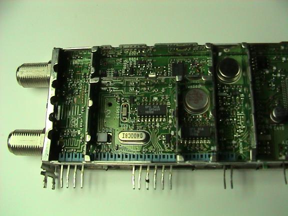
One can is the 480MHz SAW IF filter and the other a SAW resonator for the
second (fixed) LO.
I've bought these at the Pordenone flea market (NE Italy) where they were
sold for 3 euro each or four for ten. I only bought them because I have an
idea of removing the first conversion stage and using them as direct conversion
frontends for a 400...450 MHz band SIDI. But that's just an idea for now,
so if you want to build a "classic" SIDI, stay away from tuners containing
round metal cans...
In the mean time (until the direct conversion tuners hit the flea markets)
the only alternative solution I could think of was to find the cheapest
widely available consumer item that contains a suitable tuner.
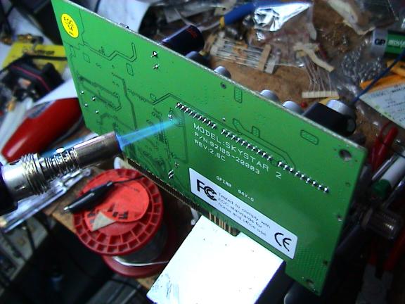
The cheapest thing I could find that contained a suitable tuner was
the "Sky Star 2" PCI card that is used for reception of digital TV
and/or data broadcasts from satellites with a PC. It loks like this:
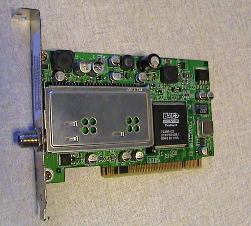
It costs cca 70 euro, not really much cheaper than the cheapest set-top boxes.
First I tried to see if the tuner is of the right (direct conversion) type, so I
could eventually return the cards for refund if the tuner was not suitable.
But removing the top cover of the tuner only revealed the bottom side of its
PCB:
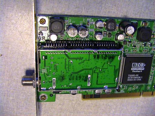
so I would have to remove the tuner to see its guts - making a return impossible.
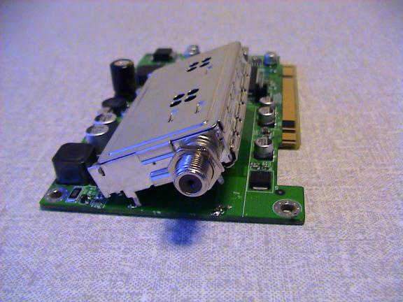
I started by removing the metal plate (two screws plus the nut on the F
connector):

Besides the electrical connections, the tuner is fixed to the PCB using
four metal pins (extensions from the rim shield) soldered through holes.
Wedging a screwdriver under the tuner like this:

and working the four pins in a roun-robin fashion with a soldering iron, it is
possible to lift the tuner like this:
Now it remains to unsolder the row of pins. The problem is you need to make
the solder flow on all of the pins simultaneously. I used an Weller "Pyropen junior"
in naked flame mode (tip removed) like this:
The tuner came off quite easily, without too much damage to the board:

I bet with some practice (like removing 5 tuners) one could do it with no visible
damage at all. But in my case the boards were condemned to the dustbin anyway....
Now I got the tuner:

Looks kinda nice, eh?
It is marked "SAMSUNG DCI 1201" and "TBMU24112IMB1", but searching the web
for these strings brought nothing.
Opening it up:

I could see a Zarlink SL1935C and a SGS-Thompson STV0299B. It was easy to get
PDF's for these on the web. The first one is a complete front end that converts
from the 950..2150 MHz band directly to baseband I and Q - exactly what we need.
The second chip is a "Link Chip" (A/D converter, QPSK demodulator, FEC etc etc),
which we don't need. Above the left chip is the quartz crystal for the synthesizer
reference, which will have to be removed and replaced with an external clock.
Since I could not get the tuner datasheet, I had to find out the pin functions
by reverse engineering. First I powered up an intact SkyStar board and measured
the voltages on all of the tuner's pins, then I traced the connections from the
chips.
I only bothered to find out the pins needed to run the converter chip. I did not
further research the STV0299b, since it will have to be switched out for our
application anyway.
The tuner has one row of 28 pins (9+10+9) and if we number them sequentially
with number one closest to the F connector, I found out the following:
pin 1	DC to RF connector (LNB supply, Diseqc)
pin 2	NC?
pin 3	+5V (preamp supply)
pin 4	0V  (Gain control?)
pin 5	+5V main supply
pin 6	Ground
pin 7	+30V (varicap supply)
pin 8	I output
pin 9	Q output
.
.
.
pin 27  SDA (I2C)
pin 28  SCL (I2C)
I found out that despite the fact that the tuner includes a demodulator, the I
and Q outputs are available from the tuner.
The I2C bus from the SL chip is not connected to the tuner pins, but looped
through the STV chip. The STV does not provide a transparent loop-through
but acts as a traffic cop on the bus.
The idea is to let the SL chip hear
only the messages intended for it, thereby reducing the traffic on its I2C
pins which could increase the phase noise of the synthesizer.
In SIDI there are only the SL chips on the bus, so this feature is not needed.
Having the STV's PDF, I could have written the software to program the SL through
the STV, but since I decided to disable the STV (to reduce possible QRM),
the I2C bus had to be rewired.
So I decided to do the following modifications on the tuners:
1. Wire the I2C bus around the STV chip
2. Disconnect the I and Q from the STV chip to prevent unnecessary loading and
possible QRM
3. Because there are two tuners in a 2-channel SIDI, it is necesarry to change
the address of one of the SL chips so they can coexist on the same bus.
4. Remove the reference quartz and make an external clock input.
5. Sever the clock line to the STV chip
The components in the tuner are of 0402 size, so before starting with the work,
do have a beer or whatever it takes to sharpen your eyes and stop your fingers
trembling.
Luckily, most of the lines have series resistors for QRM reduction, so suitable
solder pads are available for the modifications. I have left the series resistors
in the I2C lines - just 'lifted' the resistors so that they stand on one end and
connected the wires to theit top.
I have marked the resistors that have to be lifted or removed in the following
picture (before modification):

Red dots: remove resistor (I and Q to STV)
Orange dots: remove resistor (I2C between SL and STV)
Yellow dots: lift the resistors and leave them standing on the yellow dot side (I2C to
tuner pins)
Purple dot: remove resistor (AGC from STV)
Now, using thin wire-wrap wire, connect top orange point with the resistor standing
on the left yellow dot.
Then connect the bottom orange dot with the resistor standing on the right
yellow dot.
After these mods it should look similar to this:

Maybe you can notice that I haven't totally removed the
"red" and "orange" resistors, just lifted
one side - for the extremely unlikely case that I would ever want to return
the tuners to their original state. I don't really recommend this, since it
increases the risk of accidental shorts.
Now remove the 4MHz quartz by desoldering its two terminals. This is also
a good time to cut the line that feeds the clock to the STV chip.
Next drill a 2.5 or 3mm hole into the tuner side wall, next to where the
xtal was. From the outside, solder a piece of RG181 or similar thin coax
to the wall. Connect the center conductor to the left xtal terminal
through a small 1nF capacitor:

This will be the input for the external clock.
Now in only one of the two tuners, connect pin 18 of the SL chip to
the ground (green wire):

This will change its address on the I2C bus from 1 to 0.
To test the tuner I have made a simple I2C interface using the LPT port:

1K!!!!!!!!!!!!
and wrote a simple program to control the synthesizer inside the SL1935.
Here are two versions:
BASIC version: sl1935.bas.
C version: sl1935.c.
The programs use software delay loops for I2C timing. If your computer
is too fast, the I2C timing could be above specs. If things don't work,
check SCL with an oscilloscope, it shouldn't be faster than 100kHz.
If it is, increase the counts in the delay loops.
For these tests I use old 486 laptops with DOS!
The first test that can be done is to see if the SL1935 gives ACKs.
Then try if the synthesizer locks.
NOTE: for this to work, the SL1935 needs a clock! Either
do this before you remove the quartz or supply a suitable external clock -
a sinewave between 0.2 and 0.5Vpp. If the frequency is not 4MHz, change
the appropriate constant in the program.
I did not have a 30V supply handy for the varicaps, so I just connected 12V
to pin 7.
The SL1935 uses two VCO's to cover the full 950...2150MHz range, the first
covers 950...1500 and the second 1400...2150MHz, when 30V is applied to pin 7.
With 12V on pin 7 I found out (by programming increasing frequencies and
watching the LOCK status) that the oscillators will cover cca 900...1320
and 1400...1800 MHz.
Since this covers most of the interesting frequencies (H and OH astro bands,
23cm HAM band, GPS L1 and L2 frequencies, WX sats at 1.7GHz...) I decided
not to bother with a 30V supply. The working frequency of a 30V converter
would fall inside the baseband - that would be asking for trouble.
The "hole" between the two oscillators disappears at cca 16V on pin 7.
The rest of the SIDI v1.1 electronics will survive 16V (tuners and TCXO
are fed via 7805, the TBA120 and LM319 both have 18V absolute maximum supply)
It is assumed that the SIDI runs from a nominal 12V master supply, for portability
reasons.
The "upper" oscillator can have some trouble covering the 1400...1450MHz range,
so raising the voltage and using the "lower" oscillator to cover this
range could have some benefits.
SOME PITFALLS AND DEFICIENCIES
Baseband path selection
The SL1935 has built in I2C programmable switches to select between
two IF paths (lowpass filters). In the above described tuner only
one of them is implemented. (BS bit = 1)
I spent one afternoon banging my head into the wall because there was
no signal coming through, before I rememberd about that BS and changed the
program accordingly!
Reference frequency division
The minimum frequency division ratio in the reference path in the SL1935
is 2.
Such frequency division brings phase ambiguity. When dividing a frequency
by N, the counter used for division can reset (go through the "zero" state)
on any of the N cycles of the input waveform that constitute one output cycle.
One way of compensating for this is to use only such main divisor ratios
that are a multiples of the reference division ratio to "cancel it out".
This makes the smallest
possible frequency step equal to the input reference frequency.
The SL1935 chips also offer the option to put the internally divided reference
frequency (phase comparator frequency) onto an output pin that could be used
to synchronize multiple SL1935s.
However for most of the simple interferometric experiments, this phase
ambiguity is not a problem. It will only show itself when full phase
calibration (for imaging, for example) is attempted.
Poor shielding
The tuner pins have no feed-thru capacitors, so the overall shielding of these
tuners is quite poor, despite the nice shiny box.
When I used them without additional shielding/filtering, I got full scale
correlation on the 950 and 1800 MHz GSM bands, even with nothing connected
to the tuner inputs!
Back to SIDI V1.1 Page
Copyright info