A 400...440 MHz front end for SIDI
WARNING! This project is about modifying RF circuits
and requires some SMD surgery at the 0402 level, so it might not be
suitable for the bloodiest of beginners....
To make it as easy as possible, I've included a lot of photos. Of course
these are specific to the particular type of tuner I happened to come
across at the fleamarket - it is not very likely that everybody will
be able to get the same type. If it is based on the same chips, it
shouldn't be too different, though.
So if you plan to make this frontend, I strongly suggest looking for
a tuner based on SL1710. The type of the synthesizer chip is not that
important - however you will need a different software, if your synth
is not SP5659. Some synth chips (like SP5055) have inferior
performance compared to SP5659.
What tuners are suitable
On many occasions, tuners for digital satellite tv based on the
double conversion approach (first 950...2150 MHz to 480 MHz, and
then 480 MHz to baseband) can be found cheap at the fleamarkets.
They contain useful stuff, so I tend to buy them.
I've bought two types:

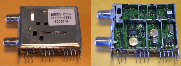
The top one is marked "SONY BCN EB8F11 DQV-AE101F", and the bottom
one is marked "BSDE5-255A" - don't know who is the manufacturer of the latter one.
Both use SP5659 for the first LO synth and SL1710 for the second conversion,
with an SAW resonator LO.
NOTE:
Later I have found out, that the top "SONY" tuner also exists in a version with the SP5655 synthesizer chip - this one has much worse phase noise, and I do not recommend it for interferometer use!
While these tuners could be used as 950...2150 MHz frontends for SIDI by
locking the second LO, I prefer the direct conversion types
(950...2150 directly to baseband) for that.
It wouldn't be THAT difficult to lock the second LO - the SL1710 provides
a 1/32 prescaler output, 15MHz in our case, so one would have to make
the LO tunable a bit and then lock the 15 MHz output with an HC161 as
divide by 3 and an HC4046 as a phase detector - but I want to keep SIDI
as easy to make as possible, so I havent gone this way.
But it soon dawned on me that the SL1710 would be a perfect direct conversion
frontend for the 350...500 MHz band, for which it is designed. All that one
would have to do is to replace the fixed 480MHz SAW oscillator with a
VCO synthesized to a common reference - and the SP5659 already in the tuner
could be used for that!
After studying the two tuners, I decided to go with the SONY tuner, because
it's layout was more suitable for this modification.
On the photo of the BSDE tuner you can see that the
480MHz IF strip, which will become the input section, (note the SAW filter) lies between the
SP5659 and SL1710 chips. This could cause LO pickup which can be a nightmare with direct conversion receivers.
In the SONY tuner
the connections between the VCO and the synth would not have to cross
the input circuits, because the SP5659 and SL1710 are in adjacent chambers.
Mechanical modification
On the right side of the tuner is the big "VLSI" chip, which is the "link"
chip, used for the demodulation of the digital satellite TV signals.
It is useless for interferometry, and the long tuner package didn't fit
the layout of my SIDI 1.1 box, so I decided to make a small mechanical
modification, this way:

Of course I have first checked that no connections important for the
RF part go through the right chamber, and removed the SMD components
which are ceramic and could damage the saw. The cut goes to the right
of the dividing wall, so that the tuner stays shielded, like this:

Also looks much nicer this way, the proportions much closer to the golden rule...
The pinout of the reaminig part is like this:
if you position the tuner, so that the pins are downwards and the F connector is to the left, and then number the pins from left to right 1...12 then the pin functions are:
1.  DC LNB1		(upper F connector)
2.  +5v preamplifier	(won't be used after the mod)
3.  DC LNB2		(lower F connector, won't be used)
4.  +5V

5.  +5V
6.  +varicap		(30V for full band, we'll use 12V)
7.  address input	(ground => adr=      => adr=)
8.  SDA
9.  SCL
10. AGC

11. originally connected to the link chip, will be used as I output
12. originally connected to the link chip, will be used as Q output
Electrical modifications
First, both SAW devices have to be removed. The LO resonator will be
replaced by a tunable LC circuit for the VCO, and the pads where the
filter was soldered will make a nice entry point for the received
RF signal. The SAW filter has cca 25...30 MHz bandwidth centerd
around 480 MHz,
which does not include the most interesting frequencies - my plan is
to include at least the 408MHz astro band and the 435MHz HAM band, for
which radio amateurs have nice big antennas.
After removing the SAW devices, the board looks like this:

Besides the pins, the cans are also soldered to the board at the tabs (where the holes are on the white circles on the picture above) and have to be
desoldered from below, through the holes, with a desoldering sucking
device.
Next step is to build a new resonant circuit for the oscillator inside
the SL1710. The change is shown below:

After removal of SAW, but before other modifications the SL1710 chamber
looks like this:

Immediately above the SL1710 are the two series capacitors, and above
them are the 390 ohm (black) and 0 ohm (black and white) resistors.
These two resistors will be replaced by the varicap diode and a capacitor
in series with it.
Besides that we need to add two 10K resistors to bring the tuning voltage
to the varicap.
After removing the two original resistors, the situation looks like this:

All of the components needed for this modification are available in the
unused part of the tuner (the 950...2150 MHz input circuits and first
conversion) in the left and top chambers below:

The red arrow shows the varicap, the magenta ones the resistors and the
yellow one the capacitor.
The capacitor should be at least 10..20pF, so look for an interstage
coupling (between transistors, not between tuned circuits) cap.
After soldering in the varicap and capacitor, it looks like this:

The two resistors lying in the circle haven't yet been soldered to
their place.
Note that I have scratched bare and tinned the groundplane on the lower
right of the circle, where one of the resistors will be soldered.
Next picture shows the situation after installing the resistors:

The resistor coming from between the varicap and capacitor can hardly
be seen, because it stands on its end. A wire carrying the tuning
voltage will later be soldered to its top end.
Be careful if you connect here auxiliary wires for VCO testing,
the resistor is very fragile in this position. I blew one SL1710
because the wire came off and landed on the SL chip - of course exactly
when it carried a 20V tunning voltage :-(
Next step is making the VCO coil and soldering it to place. It is a simple
small self supporting air cored coil.
Cut a 65mm long piece of 0.6 mm copper wire. On each end, remove the
lacquer and tin the wire, cca the last 3 mm.

Wind 5 turns onto a 3mm drill.

Solder this coil into the two holes where the SAW resonator was before,
(it's input and output pins, not the ground pin) like this:

All that remains to be done on the LO now is to connect the VCO to the synthesizer chip.
The relevant points on the PCB are shown below:

The red arrow shows the (red) point where RF from the VCO will be
connected to the RF input (pin 13) of the SP5659. The capacitor remains in
place, to avoid disturbing the DC bias, the wire from the VCO will
be soldered to its top end. The red cross shows where the trace from
the original VCO has to be cut.
The yellow arrow shows the (yellow) point where we'll pick up the tunning
voltage from the loop filter of the synth. Again, the resistor remains in place and the original trace has to be cut at the yellow cross.
I have made the RF pickup for the synth and the tuning voltage connection using thin (0.35mm) lacquered copper wire, like this:

The phase noise of the modified synthesizer is quite low, cca -80dBc at 10kHz offset, with 1MHz reference. It remains reasonable even with reference frequencies down to 20kHz or so. The charge pump current must be increased with lower reference frequencies, to keep the loop dynamics reasonable.
What remains to be done now, is to bring the RF from the input connector to the place, where the SAW fiter was, and to bring the I and Q outputs to the external world.
First, disconnect the center conductor of the input F connector from the PCB. Then, using a thin coax, connect the F connector to the place where the SAW filter was, like this:

Normally, one needs to make small dents into the dividing walls for the cable, so that the lid still fits tightly.
Next locate the I and Q outputs from the SL1710 (pins 2 and 7). In the original tuner, they are routed to the link chip, and one needs to find suitable places to connect some wires. In my case, the places to connect the wires were at the red points in this pic:

I just installed wires from here to the two unused pins, that were before connected to the link chip:

The frequency range of the modified tuner
My goal was to cover the 408MHz astro band and the 432MHz HAM band - but of course, the SL1710 is usable in a much wider frequency range.
With the oscillator coil as described above, and 12V varicap supply, the synth will cover about 100MHz. Playing accordeon on the coil, one can shift this range a bit up and down. I prefer to set it to cca 340...440MHz, in this case the coil is stretched to have the wire spacing approximately equal to wire diameter, this is also the situation shown in the above photos.
Squeezing the coil, 300MHz can be reached at the lower end, and stretching it, 500MHz at the upper end. Raising the varicap supply voltage will raise the upper frequency limit even further.
Replacing the coil with a different one, the oscillator can be made to work in an even wider range of frequencies, but the limits of SL1710 usability are set by the bandwidth of its internal quadrature splitter.
SL1710 itself is specified to have quadrature within 2 degrees between 350 and 500 MHz. I have tried to run it on 220 and 680 MHz, and the phase error (very rougly estimated on an oscilloscope) was cca 25 degrees at 220, and cca 17 degrees at 680.
I guess it would be almost perfect on the 325MHz band, and more or less usable on the 610MHz band.
Gain, bandwidth, noise figure and dynamic range
Because we have removed a significant part of the signal path, the gain of the modified tuner is lower than originally.
The gain is from 25dB at Vagc < 1.1V to 65dB at Vagc > 2.6V.
However, I do not recommend running the tuner with Vagc below cca 1.3V (which corresponds to cca 35dB of gain), because the saturation level of the outputs decreases!
With Vagc > 1.3V the tuner saturates at cca 2.8Vpp I/Q output, but with lower agc voltage, the saturation can be below 1V.
There is no significant gain variation between 330 and 440MHz (much less than 1dB).
The -3dB bandwidth at the I and Q outputs is cca 24MHz.
The output impedance of the I and Q outputs is cca 10ohm, but they must not be loaded by less than cca 200ohm, otherwise severe distortion occurs.
The output noise on the I/Q outputs, when operated at maximum gain (Vagc > 2.3V) is cca 100mV. Considering 65dB of gain and 50MHz of BW, this corresponds to cca 25dB noise figure (10000K).
Reducing the gain with Vagc, the nosie figure increases almost proportionally to gain reduction! At Vagc = 1.1V it reaches cca 41dB, or 3.7MK.
When operating at max gain, to keep the second stage contribution to less than 10K, at least 30dB of LNA gain is needed, if there are no losses between LNA and tuner. Otherwise, add the cable loss to the required gain (30dB + cable loss).
Phase noise
Because of the lower division ratio, the overall loop gain of the synthesizer is increased - so with unchanged loop filter, the loop is underdamped, and the noise spectrum has "ears", even with the lowest charge pump current setting.
On the other hand, the overall phase noise level, with 1MHz reference frequency, is pretty respectable, cca -80 dBc at 10kHz offset. The "ears" are at cca 6 kHz offset, cca 60dBc dB high.

Close-in spectrum:

(NOTE: better supply filtering would reduce the 50Hz spurs...)
I have also tried lower reference frequencies, and the phase noise was still quite OK, even at 12.5 kHz reference! With charge pump current set to max, the phase noise is still cca -80dBc at 10kHz. Note that here the loop filter is waaay off the optimum!

Close-in spectrum:

(NOTE: better supply filtering would reduce the 50Hz spurs...)
This would be useful for software radio experiments with the I and Q outputs connected to sound card inputs, where the 12.5 kHz step would provide continous frequency coverage.
Input selectivity
Well, there is none in the tuner now... Therefore I recommend at least a little external filtering (like a narrowband LNA), to avoid problems with out of band signals (which can be pretty strong in the band around 400MHz!) driving the tuner into nonlinear problems.
An even better solution would be to put some real filter between the LNA and the tuner.
Up to SIDI 1.1 Page
Copyright info