Javornik-2017: Ultra High Performance 2m Contest Setup
1. Introduction
VHF contests in Europe are big fun. While there might be various motivations to operate VHF contest, this article addresses challenges of top contesters and tries to answer THE question: "How can I make better score next year?".
Overall strategy to work more stations is nothing new - let everbody hear your signal loud enough all the time and try to receive all the callers at every time. There has been no winning station for the last 40 years or so that did not use this strategy, first starting with employing two antenna systems and then increasing number of antennas to 5, 6, 7 and even more.
As the regular troposcatter propagation allows for maximum contacts hops (QRB) of around 800 km with an average in the 400 km range, it is clear that one needs to set up his contest location at the optimum distance point from main activity centers (more information can be found in the article "IARU R1 VHF Contest - Far and wide from 2007 to 2014"). Due to relatively short distances involved this means that direct competitors (= using similar equipment) can be relatively close. Relatively close should be read as "within the radio line of sight" - radio horizon from 1000 m hill top is about 130 km away, meaning that two stations at 1000 m altitude and 260 km apart could still be in radio line of sight when their horizon is at sea level! Even if such conditions rarely exist, having competitor(s) in line of sight path of 100 km is not uncommon. Now, having high power station 100km away that uses one antenna system is something completely different then when using 6 antenna systems with some being in fixed direction - if this fixed direction is toward your station then high quality equipment needs to be used at both sides to avoid interference. Last few years there have been many articles disucssing this topic accross the Europe, so there is no need to repeat it here. Only final note, currently the main limitation of the VHF contests setups is phase noise of various local oscillators, which on transmit manifests as high TX noise and on receive as a reciprocial mixing (note to the note: required dynamic range on VHF as compared to HF is approximately 20 dB higher due to 20 dB lower environment (antenna) noise).
The concept is built around the strategy of transmitting and receiving in all (relevant) directions all the time. There is more than one way how to implement this strategy:
Main drawback of the first option is that interference levels on RX would be just too high to be manageable (one can view directional antenna as a spatial anti-interference filter).
The difference between the second and the third option is mainly the complication associated with designing and building omnidirectional horizontaly polarized antenna of gain high enough (15 dBi or more). And as one needs to install many directional antennas for RX anyway, the third option is THE option. The challenge of omnidirectional antenna then translates into efficiently feeding all those directional antennas with high enough TX power (i.e. 100W is not enough).
3. RX Challenges
Being efficient in operating more than one RX antenna is inversely correlated with the number of antennas. That is, two, three and possibly four antennas can be served by a single operator quite efficiently, but adding more antennas opens a need for another operator. Why? While one might attempt to combine all of the RX antennas together to the same 144 MHz receiver (as is usually the case on HF) this is not a good practice on VHF due to:
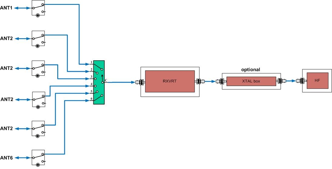
The basic RX setup for 6 RX antennas would be of the simplest form as shown on the diagram below:
Each antenna is connected to its RX/TX high power relay and then each RX line is connected to 6:1 selection switch that feeds RX converter, optional XTAL box (IF preselector) and finally the HF receiver. The time to scan through all 6 antennas is approaching 6 seconds which is a looong time (even for VHF operators, hi).
The Javornik-144/14 transverter, concieved 20 years back, together with dual receive capabilities of FT-1000mp of that time, was to greatly improve operational efficiency with two RX antennas. Adding third and fourth antenna can be attacked by using two (synchronous) Javorniks as shown on the S59DEM VHF Contest Setup page.
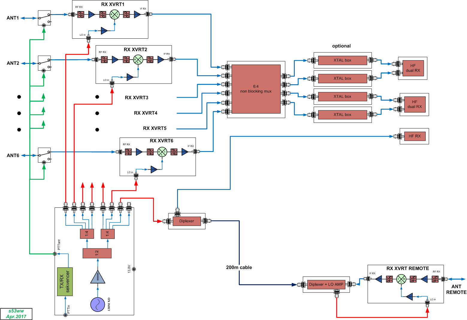
Adding even more RX antennas becomes complicated and therefore a new "VHF Contest Setup" concept was born:
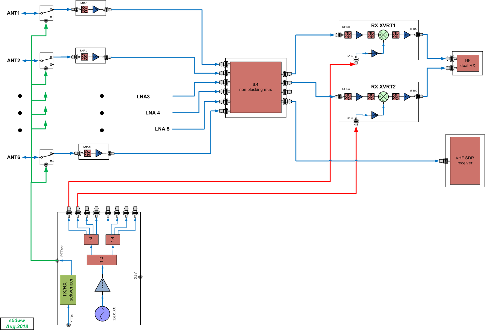
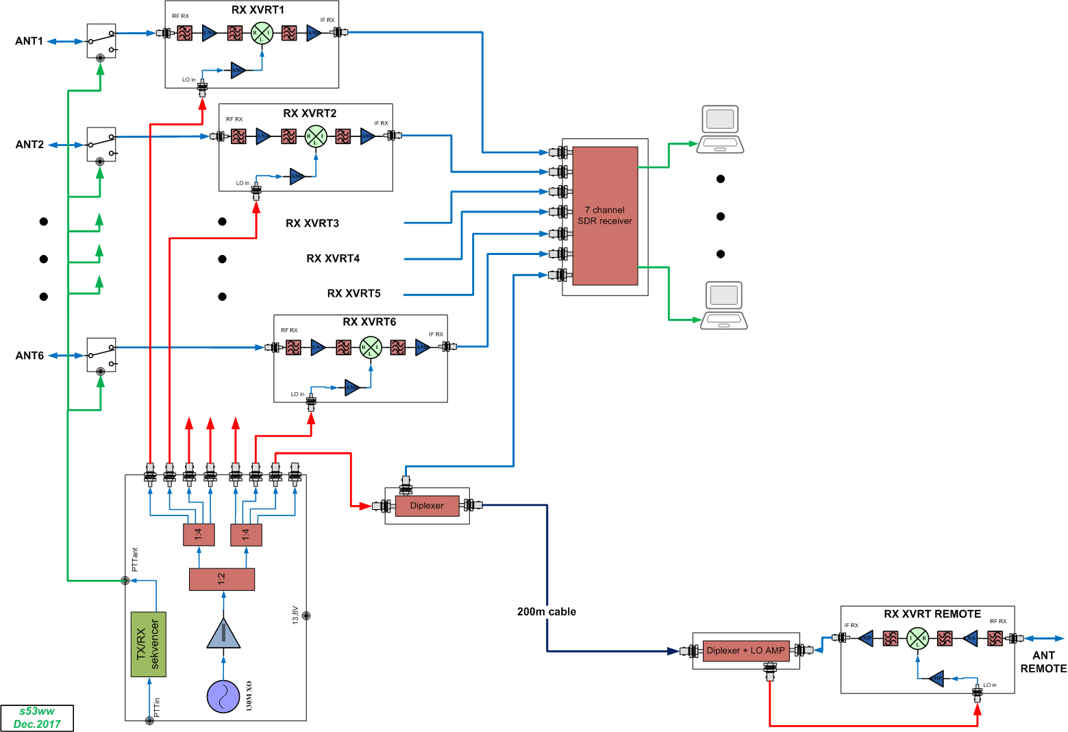
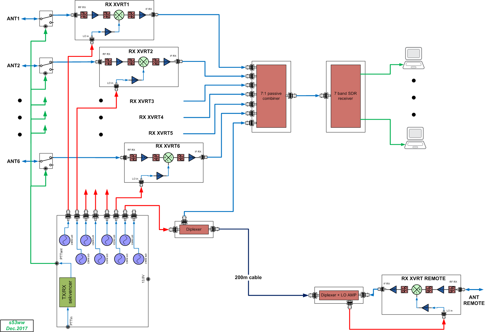
In this case single channel SDR receiver with multiband receiving function (similar to CW skimmer with QS1R) can be effectively used in the same way as N-channel SDR receiver. If the location is far away from strong stations so that LO phase noise is not an issue, the LOs could be generated with DDS that has multiple outputs or something similar.
The SDR approach offers far greater flexibility for advanced signal processing, like automatic interference reduction or antenna gain increase by automatic inphase combining of signals from individual RX antennas.
4. LO
The main module (the heart) of the concept is the LO. Beside being an ultra low noise crystal oscillator it also serves as a TX/RX sequencer and 12V power supply to the RX converters (RX converters only need 3 coaxial connections and can be placed anywhere, i.e. directly on the high power TX/RX relay, for example).5. 6:4 non-blocking switch matrix
7. RX Converter
8. TX Converter
... is WIP .
9. HF TRX
The HF TRX needs to provide adequate performance (especially the TX phase noise needs to be as low as possible). Required performance is largely driven by the use or not use of the IF preselector(s). Top contest station radiating into a wide azimuth should use IF preselector at least on the TX side all the time! On the RX side, the HF RX performance can be moderate when preceeded by the IF preselector. Due to additional IF loss (RX matrix and IF preselector), the HF RX would be operated with the PreAMP switched in. As various HF receivers provide very different NF and IIP3 levels (and usually have more than one PreAMP), one needs to carefully configure the HF RX not to degrade the system level NF and IIP3.