Very High Performance Transverter for 144 MHz
1. Introduction
JAVORNIK-144/14 is a very high performance transverter for 144 MHz optimized for use with the FT-1000MP as a 14 MHz base station and 0,5 dB of cable loss from the antenna to the RX converter input (no additional RX preamplifiers should be used!!!).
It has two (synchronous) receive converters with enough gain to overcome the 18 dB of FT-1000MP's noise figure (in IPO ON state). The FT-1000MP should be slightly modified to use the second RX converer of the JAVORNIK-144/14 (the SUB RX path should be broken and brought to the back panel - an easy modification that can do no harm to the RIG).
The local oscillator (130 MHz) is based on the Buttler design using low noise transistors BFR93a. It has two separate paths feeding two RX mixers. Maximum LO power is 23 dBm and can be controlled with attenuator in front of the mixer (different types of mixers can be used). When not attempting to build both RX converters only one LO PA path should be constructed.
The TX converter accepts the 14 MHz IF signal levels from -20 dBm to +20 dBm. Driver is designed with BFG196 working in class A and delivering very clean +15 dBm signal that drives the Mitsubishi module M57727 (20 W out) or M57713 (10 W out).


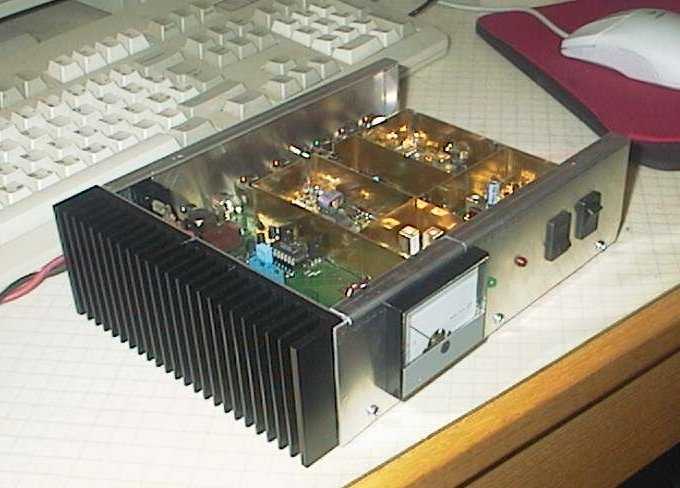
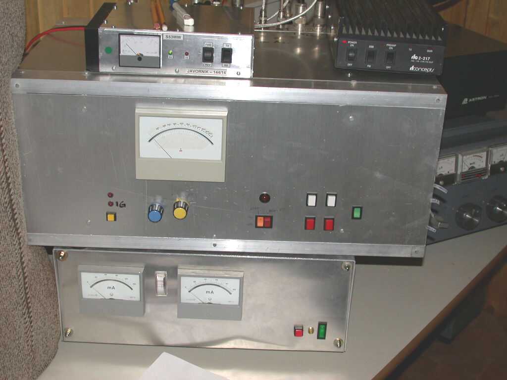
Fig.1: JAVORNIK-144/14 prototype (left) and during the year 2002 VHF contests from JN75DS.
2. RX Converter
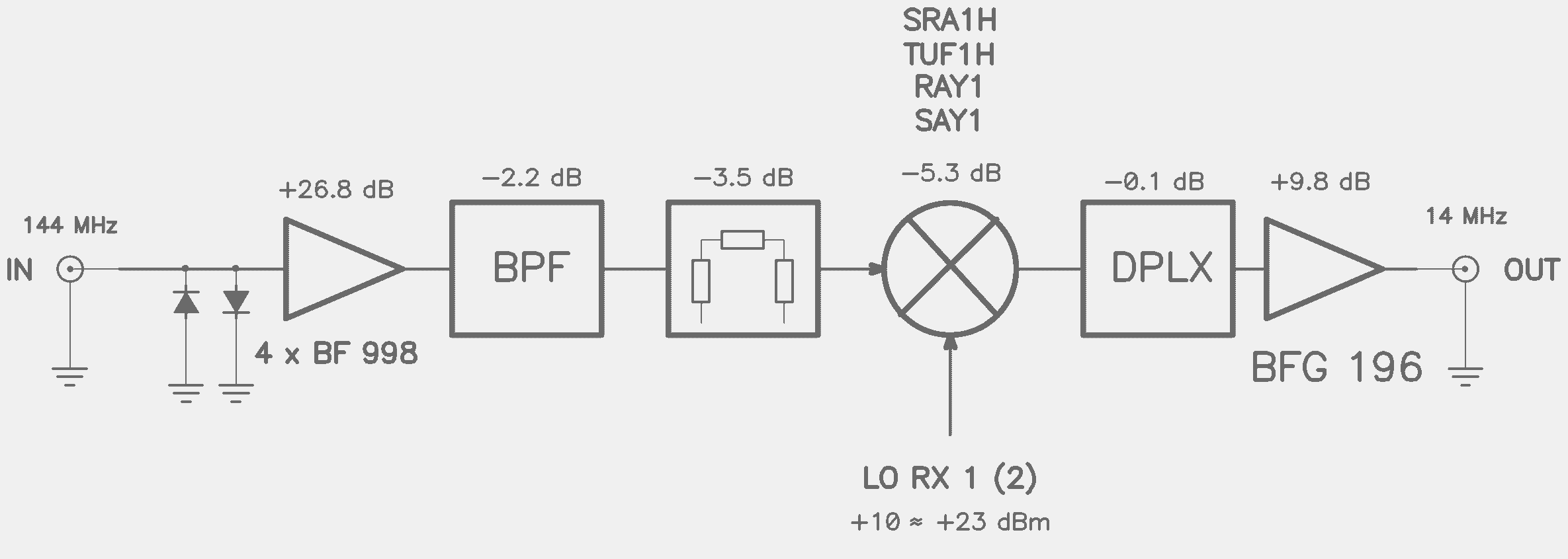
Fig.2: the RX converter block diagram (shematics of RX converter, 1, 2)..
The overall NF of the RX system (0,5 dB of cable loss + XVRT + IF RIG) is aimed at the 2,0 dB (170 K) what is more than needed for even the most demanding tropo work on 144 MHz. The 0,5 dB of cable loss can be acheived with 33m of 7/8" cable or 18m of 1/2" cable or 11m of AircomPlus/H2000 cable. Remember that the investment in a good (read: thick) cable is much more worth than spending the same amount of money for a mast mount preamplifier!!! For those that have really long cable runs the JAVORNIK-144/14 has a layout prepared to install the 4xBF998 preamplifier at the antenna port (DC is supplied via RX or RX/TX coaxial cable).
Table 1: RX technical data of JAVORNIK-144/14.
|
JAVORNIK-144/14 |
JAVORNIK-144/14 + FT-1000MP (IPO ON, MAIN RX) |
|
|
NF |
0,9 dB |
1,5 dB |
|
G |
25,0 dB |
- |
|
input IP3 |
+ 4 dBm |
- 2 dBm (@15 kHz, calculated, based on my measurement of IP3 at 14 MHz) |
Transverter gain should be set to proper value (by changing the attenuator in front of mixer RF input) when using other types of IF RIG's so that the overall dynamic range is optimized. Table 2 gives the required values of the PI attenuator (R's to ground/series R) for various IF RIG NF's so that the overall NF will be 1,5 dB.
Table 2: values of the PI attenuator in front of the RX mixer to achieve the overall NF of 1,5 dB.
| G [dB] |
NF [dB] |
T [K] |
IP3out [dBm] |
ATT [dB] |
PI ATT R values |
IF RIG NF [dB] |
|
26,5 |
0,75 |
55 |
30 |
2,5 |
330/15 |
20 |
|
26,0 |
0,8 |
58 |
30 |
3,0 |
300/18 |
19 |
|
25,5 |
0,85 |
63 |
30 |
3,5 |
270/22 |
18 |
|
25,0 |
0,9 |
67 |
29 |
4,0 |
240/27 |
18 |
|
24,5 |
0,95 |
71 |
29 |
4,5 |
220/30 |
17 |
|
24,0 |
1,0 |
75 |
29 |
5,0 |
200/33 |
16 |
|
23,5 |
1,05 |
79 |
29 |
5,5 |
180/36 |
15 |
|
23,0 |
1,1 |
84 |
28 |
6,0 |
150/39 |
14 |
|
22,5 |
1,2 |
92 |
28 |
6,5 |
150/43 |
13 |
|
22,0 |
1,3 |
101 |
28 |
7,0 |
135/47 |
11 |
|
21,5 |
1,35 |
106 |
28 |
7,5 |
130/51 |
9 |
|
21,0 |
1,45 |
115 |
27 |
8,0 |
120/56 |
5 |
When the cable loss between the antenna and RX is highier than 0,5 dB one can calculate the required RX conveter gain G to get the required NF of 2,0 dB (T = 170 K) using the following formula:
TIF/G + TRX = T
T = 170 - 290*(10L/10 - 1)
where TIF = 290*(10NF/10 - 1) and TRX is a function of G as given in the Table 2.
For example: TIF = 11200 K (16 dB) and L = 0,8 dB ==> T = (170 - 58) = 111 ==> trying first with a pair of G = 446 (26,5 dB) and TRX = 55 K on gets T = 80 what is too low, so we try with the next value of Table 2, and so on, until we find the pair G = 281 (24,5 dB) and TRX = 71 K that satisfies both equations.
Finding the value of NF for HF RIG is not so trivial as one might think. RIG reviews as done by G3SJX and ARRL give the sensitivity numbers, G3SJX for 10 dB of (S+N)/N on SSB (BW = 2,4 kHz) and ARRL for 0 dB of S/N on CW (BW = 500 Hz). Assuming that the noise bandwith is the same as that of IF filters (i.e. 2400/500 Hz) one can easly calculate the NF from those numbers (i.e. for ARRL data: NF = MDS - (-174 + 10LOG(BW))). BUT the noise BW is not the same; this fact can be seen when comparing G3SJX and ARRL data. Table 3 gives the comparison of some calculated NF's of few HF RIG's. The noise BW is clearly affected by the AF circuitry. One would say that the NF's calculated from G3SJX sensitivity data are too optimistic as the AF circuitry response narrows the noise BW although some numbers do not reveal this fact (IC-775, TS-870) .
Table 3: NF values of different HF RIG's on 14 MHz in AIP ON state (preamplifier off) as calculated from G3SJX and ARRL measurements and assuming IF filter bandwidth as noise bandwith.
|
HF RIG |
NF [dB] from G3SJX data (BW = 2,4 kHz) |
NF [dB] from ARRL data (BW = 500 Hz) |
|
FT-1000MP |
16 |
19 |
|
FT-1000MP MARK-V |
17 |
20 |
|
TS-870 |
18 |
18 |
|
IC-775DSP |
12 |
9 |
|
IC-756PRO |
12 |
13 |
|
IC-738/736 |
12 |
14 |
Now, why 14 MHz for IF instead of standard 28 MHz? Because the linearity of HF RIG receivers is optimized for 7 MHz and14 MHz band. Linearity on lower bands can be improved with attenuator without loosing the sensitivity. On higher bands linearity of some RIG's is worse (without any good technical reason). Particulary on newer RIG's the linearity on 28 MHz is very bad (with the exception of TS870). Table 4 gives some comparative numbers on IP3 of various HF RIG's.
Table 4: IP3 values of different HF RIG's on 14 MHz and 28 MHz in AIP ON state (preamplifier off) as taken from G3SJX data (50 kHz tone spacing).
|
HF RIG |
IP3 [dBm] @ 14 MHz |
IP3 [dBm] @ 28 MHz |
|
FT-1000MP |
24 |
6 |
|
FT-1000MP MARK-V |
24 |
2 |
|
TS-870 |
17 |
20 |
|
TS-850 |
25 |
16 |
|
IC-775DSP |
12 |
1 |
|
IC-756PRO |
13 |
14 |
|
IC-738/736 |
21 |
22 |
Now let's compare some figures of VHF contest setup with 0,5 dB of cable loss, XVRT and HF RIG using JAVORNIK-144/14 and LT2S. LT2S is recognized as some kind of XVRT "standard": it has 20 dB of gain, 1,0 dB of NF and IP3out of +27 dBm. Table 5 gives the data of NF and IP3in when using JAVORNIK-144/14 and LT2S with different HF RIG's (NF and IP3 data are taken from Tables 3 and 4). Because LT2S has too low gain for some HF RIG's the overall sensitivity may also be too low (depending on the antenna noise temperature, which is geographically dependent). The data in parenthesis are for JAVORNIK-144/14 with gain set to the value that gives the same NF as with LT2S. The values of JAVORNIK-144/14 gain is given in a separate column. Carefully comparing the data one can see how the gain and NF of the XVRT influences the figures of merit of the complete RX system.
For example, taking FT-1000MP as IF RIG with LT2S one might think that his sensitivity is too low and he immediately adds the preamplifier at the antenna with 10 dB of gain. The linearity is spoiled in that way for 10 dB (IP3in = -23 dBm) even if the preamplifier is perfectly linear. Or one can switch-on the FT-1000MP's preamplifier (IPO OFF) - in that way the IF NF goes from 18 dB to 8 dB and overall NF goes from 3,2 dB to 1,7 dB; but the IP3 also goes from +6 dBm to -1 dBm and again the overall linearity goes down to the value of -20 dBm.One can conclude from the data of Table 5 that LT2S can be used with advantage only with HF radios that have NF in the order of 10-14 dB and IP3 values of some +20 dBm (on 28 MHz !!!).
Table 5: NF and IP3 values when using JAVORNIK-144/14 on 14 MHz and LT2S on 28 MHz.
|
HF RIG
|
JAVORNIK-144/14 |
LT2S |
|||
|
NF [dB] |
IP3 [dBm] |
G [dB] |
NF [dB] |
IP3 [dBm] |
|
|
FT-1000MP |
2,0 (3,2) |
-2 (+2) |
25 (21) |
3,2 |
-13 |
|
TS-870 |
2,0 (3,2) |
-8 (-4) |
25 (21) |
3,2 |
+0 |
|
TS-850 |
2,0 (2,7) |
+0 (+2) |
24 (21) |
2,7 |
-4 |
|
IC-775DSP |
2,0 (1,8) |
-9 (-10) |
22 (23) |
1,8 |
-18 |
|
IC-756PRO |
2,0 (2,1) |
-9 (-9) |
22,5 (22) |
2,1 |
-6 |
|
IC-738/736 |
2,0 (2,2) |
-2 (-1) |
22,5 (21,5) |
2,2 |
+1 |
Talking about the required sensitivity on 144 MHz in contests one must take into the consideration his antenna noise temperature (TA). In some texts it is stated that the minimum TA on 144 MHz is 200 K when the antenna is pointing to the cold sky. Actual figures for antennas pointing toward horizon are allways highier. Figure 3 gives the measured TA at our contest location JN75DS, 1269 m asl (02.07.1999, 19:00 LT). Minimum value measured was 370 K what equals to 3,5 dB of NF. Maximum values are into the direction of the city of Postojna (about 10 km away, 500 m asl, 1600 K = 8,1 dB) and city of Cerknica/Ljubljana.
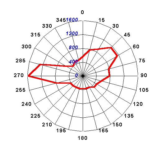
Fig.3: antenna noise temperature TA at our contest location JN75DS, 1269 m asl (02.07.1999, 19:00 LT).
It is well known fact that when the RX system noise temperature is the same as that of the antenna the S/N degradation will be 3 dB. It is of course arguable if this S/N degradation is acceptable for VHF contest RX. I took the value for TRX as the 0,6 times the value of TAmin - it gives a 2 dB of S/N degradation. And the TAmin is taken as 300/2 + 200/2 = 250 K (half of the earth and half of the sky noise). In that way the specification for the system NF is 2,0 dB (170 K) and it gives enough room for unpredictable losses of relays, short interconnection cables, etc.
3. Local Oscillator
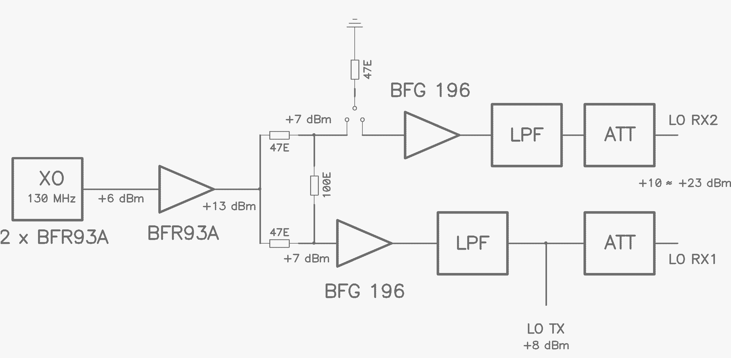
Fig.4: the LO block diagram (shematics of LO circuitry, 1, 2, T/R control, 3, and complete wiring, 4).
The local oscillator (130 MHz) is based on the Buttler design using low noise transistors BFR93a. It has two separate paths feeding two RX mixers. Maximum LO power is 23 dBm and can be controlled with attenuator in front of the mixer. Different types of mixers can be used (recommended mixer is TUF-1H). When using a 23 dBm LO mixer (i.e. RAY-1 or SAY-1) one can achieve about 1 to 2 dB increase in IP3 value (of the RX converter itself, actually the IP3 will be determined by the IF RIG as long as it is less than +25 dBm). It is not worth using RAY-1 as it has the same P1dB as TUF-1H (+14 dBm) - it is better to use SAY-1 that is specified for +20 dBm P1dB. Anyway the extra cost of +23 dBm LO mixer is not worth the 1-2 dB IP3 improvement.
When not attempting to build both RX converters only one LO path should be constructed.
4. TX Converter
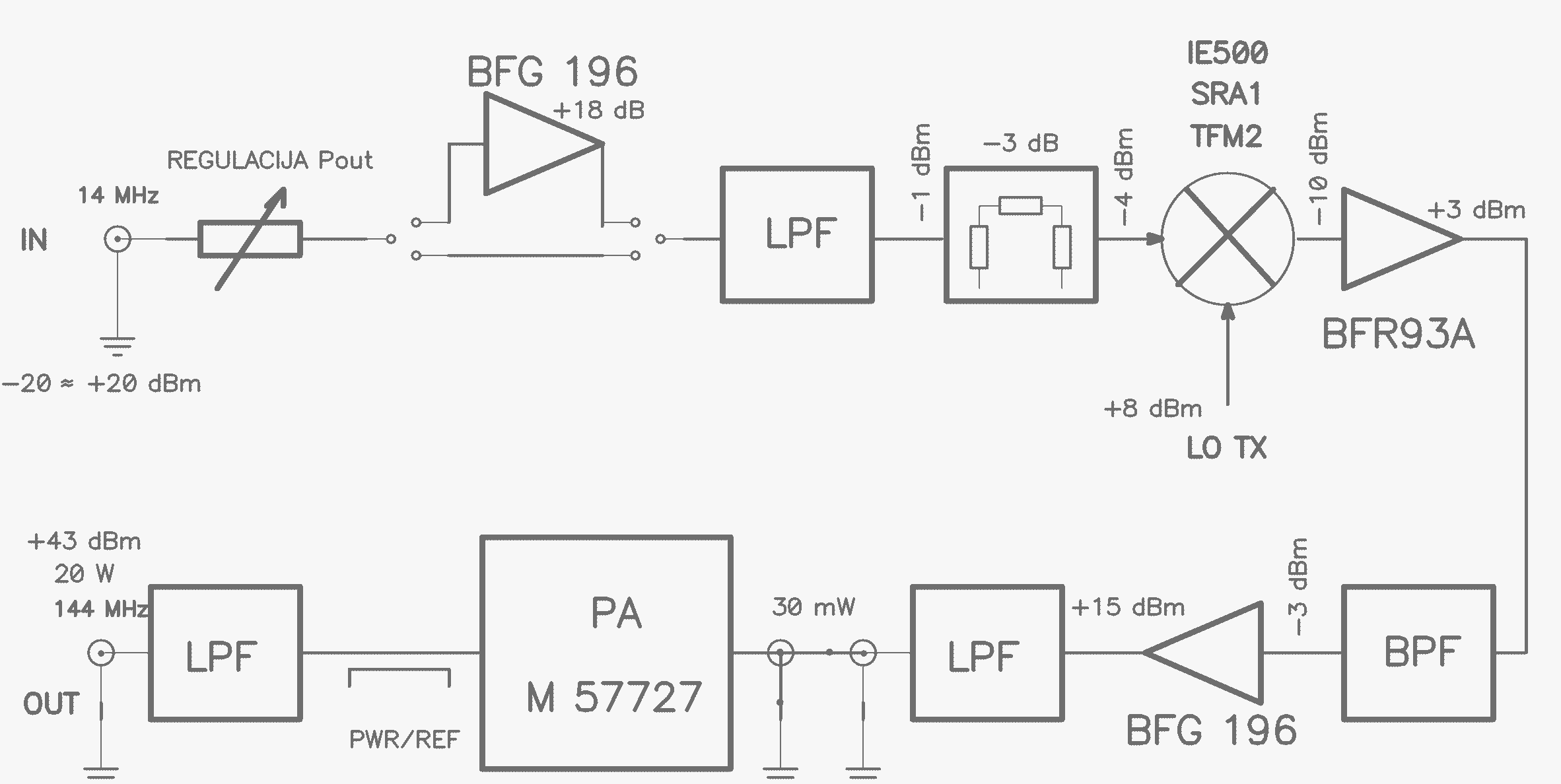
Fig.5: the TX converter block diagram (shematics of TX converter, 1, 2, 3).
The TX converter accepts the 14 MHz IF signal levels from -20 dBm to +20 dBm. It has switchable IF amplifier for those HF RIG's that have low TRV drive level (-10 to -20 dBm). It uses low level mixer followed by broadband low noise amplifier. Driver is designed with BFG196 working in class A and delivering very clean +15 dBm signal (IMD5 at -60 dBc). For the final amplifier the most cost effective and trouble-free solution is used - the Mitsubishi module M57727 (20 W out) or M57713 (10 W out). This is not the best technical solution as the modules are not among the very linear ones but when driving them at the 20/10 W or less it is easy to achieve the high order IMD products to be more than 120 dB below the carrier (that level guarantees no-splattering to the nearby stations).
The biggest problem of the overall TX chain is the composite transmit noise (wideband thermal noise and oscillator phase noise). There are two contributors to this noise, the XVRT and the HF RIG. The measured JAVORNIK-144/14 BB TX noise with 20 W out is at the -118 dBc/2,4 kHz for large 200 kHz offset (be aware that the BB TX noise will be only -108 dBc/2,4 kHz for 2 W of output power). But the level of the HF RIG BB TX noise is much much worse! Looking at the G3SJX data (ARRL measures the TX noise only up-to the 20 kHz offset) one can see that there is no modern HF RIG that has the BB TX noise level lower than -110 dBc/2,4 kHz at 200 kHz offset. And it is normally at the -100 dBc/2,4 kHz for closer spacings. It means that the transmitted S/N is only about 100-110 dB!!! Two VHF stations 100 km (!) apart (with radio visibility) with 500 W and 16 dBi antennas develop the -27 dBm input RF level - this is 111 dB above the SSB noise floor (taken as -138 dBm). Transmitting with the IF RIGthat has -111 dBc/2,4 kHz BB TX noise level rises the RX noise already by 3 dB!!!
One can conclude that the BB TX noise is the main problem in VHF contests in populated areas. For example, in S5 the medium distance between well equipped contest stations is 50 km and distances of 10-20 km are not uncommon!
5. Interfacing JAVORNIK-144/14 to FT-1000MP
In order to fully utilize the functionality of FT-1000MP with separated RX inputs one should construct an extra circuitry that interfaces the XVRT and IF RIG. As the minimum the circuit should include the cross-switch on 14 MHz so that one can switch both RX converter IF outputs to the MAIN RX input. This is necessary as the SUB RX is not of the same quality as the MAIN RX and does not have the DSP proccesing. I estimate that only some 20% of contacts would need to be switched from SUB to the MAIN RX.
The interface circuit could include additional circuitry to enable S&P operation on SUB RX on both RX converter IF outputs independently of the cross-switch, high quality NB circuitry, XTAL filters for fix frequency operation, etc.
Interface circuitry that is currently in use at S59DEM (also S55AW and S53WW) contest station can be seen on following figures: 1, 2, 3, 4. Pictures of the set-up can be seen here: A, B, C, D.
6. Further development
Regarding the problems with TX BB noise the idea is to construct the high quality 130 MHz VFO (either VXO or DDS/PLL) and use the HF RIG as a single frequency IF receiver. In that way 14 MHz crystal filter could be installed between XVRT and IF RIG on TX nad RX. One would benefit in transmit (highier TX S/N) and receive (lower IMD products).
7. KIT kompleti
Na voljo so polni KIT kompleti za JAVORNIK-144/14.
Za vse informacije/naročila glede KIT kompleta se obrni na Sineta/S53RM - s53rm@lea.hamradio.si.
8. Results of a batch of 30 xvrt's built by different home-brewers
Some 18 KIT complets were distributed to the ham radio home-brewers, 12 KIT's were built by Sine/S53RM and Franci/S51RM and one prototype by myself.
Here are the results of "measurement day" that was held on 15.02.2003 in Domzale. We measured the NF, G and IP3 of RX converters and IMD of TX converter. Other fine settings and tunings were also performed (RX and TX bandpass filter tuning, forward and reverse power meter calibration, LO frequency setting) together with some troubleshooting actions.
|
|
RX1 NF |
RX1 G |
RX2 NF |
RX2 G |
remarks |
|
s53ww |
1,0 |
25,5 |
0,9 |
25,5 |
(att. 3,5dB) |
|
s53jpq/s51rm |
0,9 |
25,5 |
0,8 |
27,0 |
|
|
s55m |
1,1 |
26,0 |
0,8 |
27,5 |
|
|
s59dhp/s57c |
1,0 |
25,0 |
0,9 |
27,0 |
|
|
s55wt |
0,8 |
27,0 |
0,9 |
25,0 |
|
|
s51vj |
1,0 |
25,5 |
0,7 |
28,5 |
|
|
s51di |
1,3 |
22,0 |
--- |
---- |
(att. 5dB) |
|
s57s/s51di |
1,4 |
23,0 |
1,4 |
23,0 |
(att. 5dB) |
|
s53d/s57msu |
1,0 |
25,5 |
0,9 |
27,5 |
|
|
s57kaa |
1,0 |
25,0 |
0,8 |
28,0 |
|
|
s52lm |
0,8 |
26,0 |
0,7 |
27,5 |
|
|
s59r/s52zo |
1,0 |
25,5 |
0,9 |
27,5 |
|
|
s50c/s57ct |
1,0 |
25,5 |
0,7 |
28,0 |
|
|
s50k/s53rm |
1,0 |
23,5 |
0,7 |
28,0 |
|
|
s53vv |
0,8 |
26,0 |
0,6 |
29,0 |
|
|
s53rm |
1,0 |
26,0 |
0,7 |
28,0 |
|
|
s53drm/s53rm |
0,8 |
26,0 |
0,6 |
29,0 |
|
|
nr.21/s53rm |
0,8 |
26,0 |
0,6 |
29,0 |
|
|
nr.22/s53rm |
0,9 |
25,5 |
0,7 |
28,0 |
|
|
nr.23/s53rm |
--- |
---- |
0,7 |
28,0 |
|
|
nr.24/s53rm |
0,9 |
25,5 |
0,7 |
28,0 |
|
|
nr.25/s53rm |
1,0 |
25,5 |
0,7 |
28,0 |
|
|
nr.26/s53rm |
0,9 |
26,5 |
0,8 |
28,5 |
Some general remarks:
1. as can be seen from results the repeatability of the design is very high.
2. the RX2 has some 2 - 3 dB highier gain as predicted (slightly different layout of 4xbf998 amp) and as a consequence RX2 NF is lower - 0,7 dB. The reason for that behaviour was found in a missing screen near the cold end of input coil, the one that is "seen" by the RX1 input coil.
3. IP3 figures were only checked to be better than +4 dBm (IP3in) as the spectrum analyzer used had no marker readout and substitution method with calibrated step attenuator was too time consuming to be performed on each XVRT.
4. it looks that the biggest problem home-brewers had is/was tuning of RX bandpass filters - it has a major impact on IP3 and stability. I recomend tuning the filters with spectrum analyzer with tracking generator. The filter has to be tuned for 6-8 MHz of 1db pass band centered at 144 MHz and that is very hard to do with FM handy and power sensor (but it can be done - I did it once, to check if it is possible, hi).
5. the input coil of 4xbf998 amplifier should not be mounted to high above the ground - 3mm is allready too high and the LNA oscillates as it gets the cover. The best position is 1-2 mm above the PCB.
6. the RX1 input through the relais has 0,1 dB of additional losses (that is 0,1 dB highier NF).
7. output IMD was checked and was in the declared limits. As it turned out the 20W is the maximum "linear" output power of the M57727 module.
8. The 4xbf998 amplifiers were found to have some stability problems. After some experimenting the cure was found in a form of a new LNA output transformer - the original 1/3 turns were changed to 2/6 turns and the RX converters are now absolutely stable!
9. Results of measurements made in Pforzheim 2005 by DF9IC
On 27th of February 2005 Henning/df9ic and the group made some very interesting measurements of different VHF RIGs nad XVRTers with HF RIGS. Some of the measurements were repeated few weeks later. See the results in those files Pforzheim2005.pdf, Pforzheim2005.xls, TRX_Messung_3_2005.xls.
Although the measurements were made by proffesional equipment, please note the measurement tolerances given on the first page of PDF file!
Here are some pictures: FT1000mp+Javornik.jpg, Orion+Javornik.jpg, DF9IC.jpg.
And here is the link to the DF9IC page with some very useful comments on the measurements and results: http://www.df9ic.de/tech/trxtest/trxtest.html
10. TX path modifications
As the M57727 power modules are obosolete for many years already, the new parts produced by Mitsubishi are now available. These are FET power modules that are pin and size/case compatible with the old ones. They are much more linear and cheaper. The output power of the RA60H1317M is 60W. This power level is just right enough to drive a 1kW triode amplifier. So the obvious thing was to make an upgrade to the Javornik-144/14 that can be of great help to some contest installations (getting rid of a "brick" amplifier between XVRT and PA).
What is to be done? Just replace the M57727 with the RA60H1317M and the 78L09 voltage regulator with the 78L05! Remove the coil (VK200) that was used to bias M57727 (pin2). Then connect together the output of 78L05 and Pin2 (where the VK200 was soldered) with a 100R resistor (note that RA60H does not have the pin3!). Also add something like 10uF capacitor from the Pin2 to the ground (in paralel with the 10nF). Now, as the RA60H has some 15dB more gain and 4dB more output power it is neccessary to lower the gain of the TX path for 11dB's. The best point to do that is just behind the driver BFG196. So a PCB line is to be cut and a PI attenuator is to be installed (3x82R).
The total power disipation on TX is now around 60W (9A at 13,6V for 60W of output power), so it is a good idea to install a small fan on the heatsink (or bigger heatsink).
I made some TX IMD measurements with the following results (spectrum analyser that I used had only about 70dB of SFDR):
| Pout | IMD3 | IMD5 | IMD7 | IMD9 | IMD11 | IMD13 | IMD15 | IMD17 | IMD19 | IMD21 |
| 60W | -18 | -30 | -38 | -44 | -48 | -54 | -58 | -62 | -66 | -70 |
| 40W | -22 | -38 | -44 | -52 | -58 | -64 | - | - | - | - |
| 20W | -28 | -42 | -52 | - | - | - | - | - | - | - |
I also repeated the TX noise measurements of the XVRT alone. The TX S/N is 120dB when not using the TXIF amplifier and 114dB when this amplifier is in line (BFG196 at 14MHz with 18dB's of gain). The value of 114dB is just about 4dB highier than the best HF RIG's TX S/N figures at the 200kHz offset (110dB for FT1000mp, but (!) about 120dB for IC7800). As the XVRT output level at various HF RIGs differs from -20dBm to +20dBm and as the input level to the TX mixer should be -5dBm (for 60W of output power), there certanly is a need to have this amplifier on board. But the position of the potentiometer for seetting the output power should be changed - it should be positioned after the amplifier (for FT1000mp there is a need for some 6dB of amplification only)! The modification can be seen on this picture IFTX_MOD.jpg. The physical position of the potentiometer can not be changed, so the pins are to be connected in a series arm of the PI atenuator with two short pieces of thin coaxial cable. With this modification the TX S/N for 60W of output power with FT1000mp is 118dB. Please note that this value will be only 108dB if running XVRT at 6W of output power!!!
11. Setting of the FT1000mp TX signal level
It was found (tnx to Ian/g0afh) that there are some high level spurious signals present at the TRV output of the FT1000mp (and probably also of the FT1000mpv) when the RF PWR control is fully opened.
Sine/s53rm made some more detailed measurements. The spurii overlap with the main carrier when the VFO is tuned at 14090kHz. By tuning up or down from this frequency the spurious signals start moving away from the carrier. Scale of the display is 1MHz/div and 10dB/div. Measurements were done for maximum levels of the spurs (RF PWR position between 09:00 an 10:00) on FT1000mpfield.
VFO at 14090kHz VFO at 14150kHz VFO at 14200kHz
VFO at 14300kHz VFO at 14400kHz
When operating between approximately 144,000MHz and 144,200MHz spurs are falling directly into the SSB/CW portion of the 2m band.
Spurs do disapear when the RF PWR control is turned CCW to the position of 08:00 o'clock.
Setting the RF PWR as shown on the picture also reduces the output level of the carrier by something like 5-6dB. It was also confirmed that this 5-6dB lower level is present at TRV port when the RIG is set for 100W output power at main antenna port. Those missing dB's are easily restored by increasing the TX gain of the XVRT. Doing so also increases the total broadband TX noise of the setup - TX BB noise increases from -118dBc/2,4kHz to -115dBc/2,4kHz. This 3dB increase in TX BB noise is a good compromise for getting cleaner output signal.
Last modification: 01.03.2003
Pictures of the interface circuitry added on 01.09.2004.
DF9IC measurements added on 22.03.2005.
Link to DF9IC web page added on 09.04.2005.
Replacing M57727 with RA60H1317M added on 12.05.2005
FT1000mp TX setting added on 16.04.2007