
(DESIGN)
(COSTAS)
(FRONTEND)
(SUPPLY)
(PCB)
(SHIELD)
(ASSEMBLY)
(TEST)
(HOME)
10Mbps BPSK ZIF transceivers for 1.2GHz, 2.3GHz and 3.4GHz
Matjaz Vidmar, S53MV
5. Printed-circuit boards
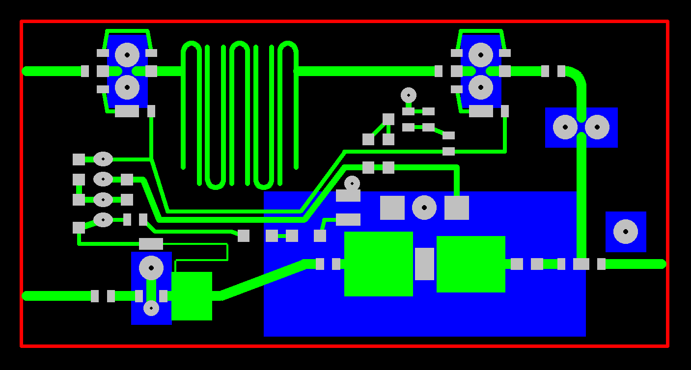
Each BPSK transceiver is built on five different printed-circuit boards. The two RF boards (ZIF+PLL+modulator and RF front end) are double-sided microstrip circuits on 0.6mm-thick FR4 laminate including a 550 micrometer thick dielectric core and 17.5 micrometer cladding on both sides for a total thickness of 585 micrometers. The dielectric constant is around 4.4 and the loss tangent is around 0.02 in the frequency range of interest.
The three low-frequency boards (Costas demodulator, RX/TX switch and power supply) are less critical single-sided boards on 0.8mm-thick FR4. All five printed-circuit boards (pcb.zip) are etched from just one side. The two doube-sided microstrip boards have the groundplane unetched. Copper is carefully removed with a 3mm drill tip around 0.8mm holes carrying supply voltages and low-frequency signals.
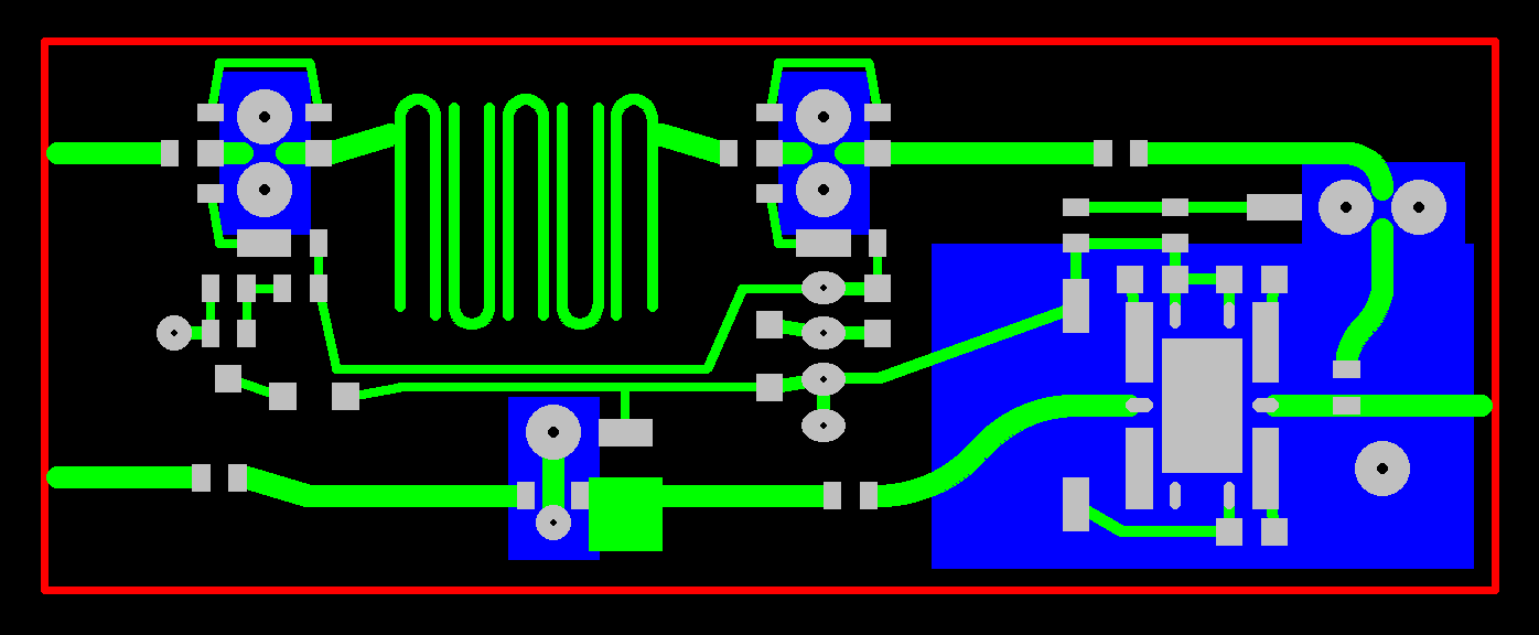
RF components on the two microstrip boards require proper grounding and proper heat removal. Without plated-through holes the suggested installation of these components is shown on the following drawing:
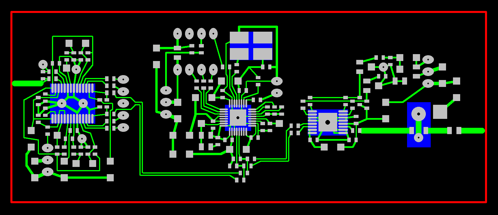
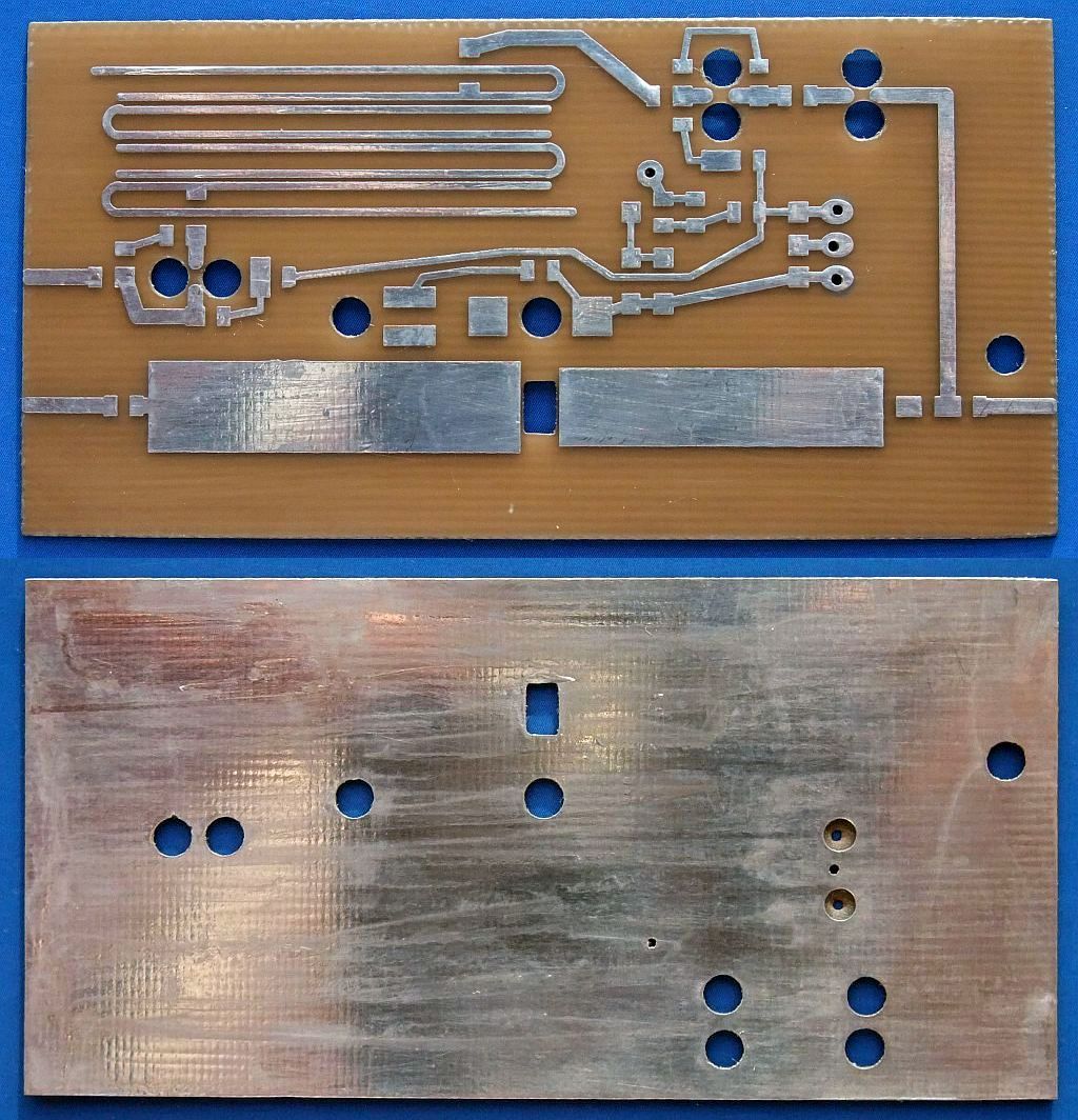
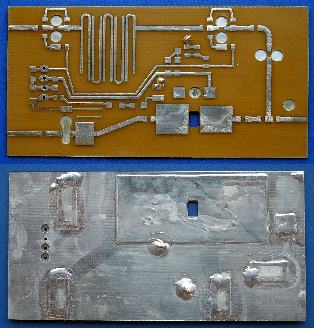
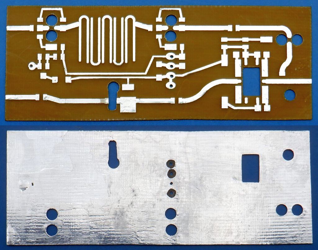
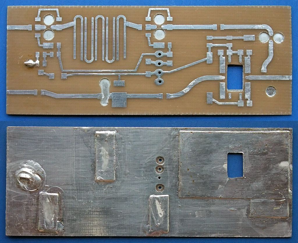
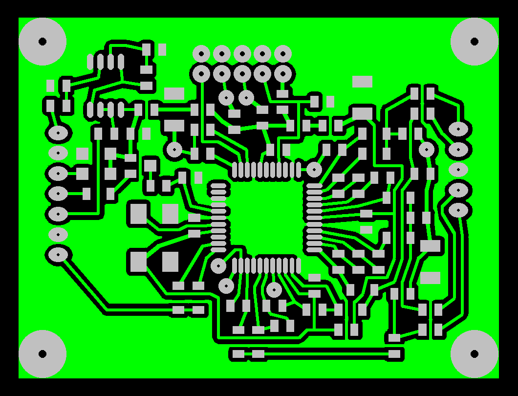
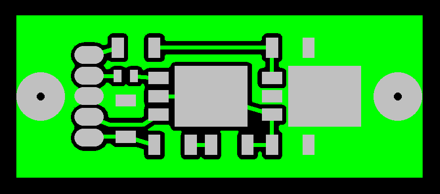
The ZIF+PLL+modulator is the most complex board:
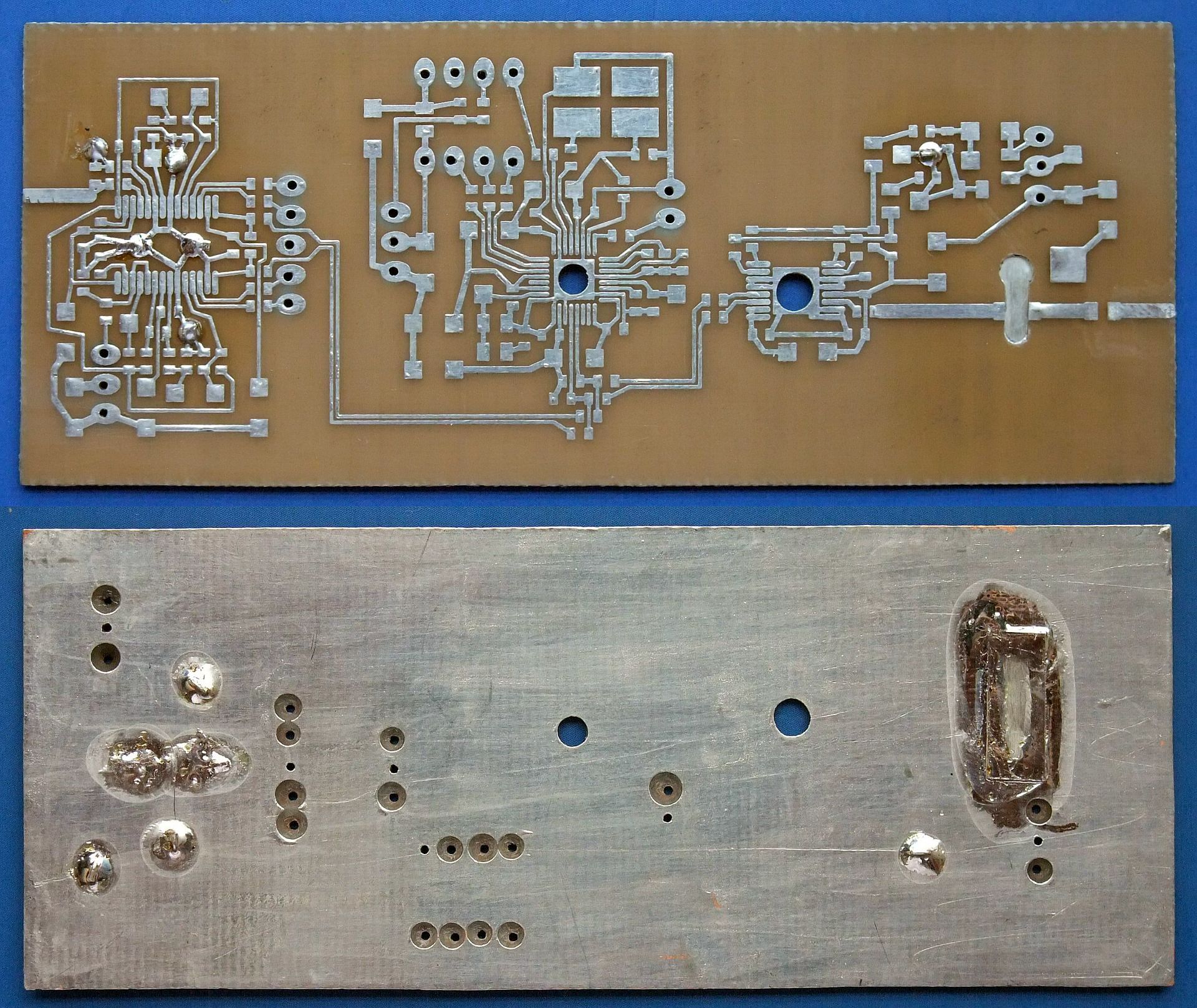
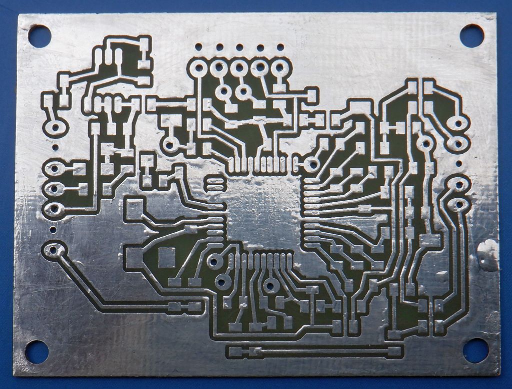
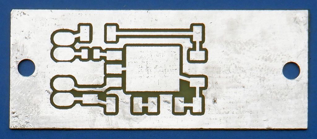
After etching and drilling, copper is removed in the ground plane around signal-carrying holes and both sides of the board are tinned using additional flux:
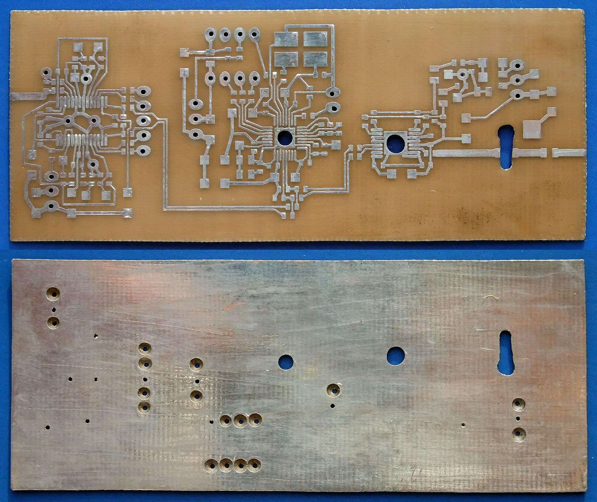
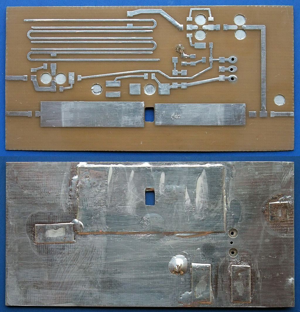
Before installing any components, the grounding holes have to be covered with 0.1mm-thick tinned copper tape. Pieces of copper wire are soldered into ground-connecting vias. The two vias under the AD8347 require particular care. The ground connections are made with small pieces of tinned copper tape using the minimum amount of solder to allow the installation of the AD8347:
The RF front end for 1.2GHz includes a band-pass filter sensitive to substrate tolerances:
After etching and drilling, copper is removed in the ground plane around signal-carrying holes and both sides of the board are tinned using additional flux:
Before installing any components, the grounding holes have to be covered with 0.1mm-thick tinned copper tape. A suitable piece of 0.2mm thick tinned copper sheet has to be soldered in place to spread the heat produced by the PTFC270101M power LDMOS transistor:
The RF front end for 2.3GHz includes a band-pass filter sensitive to substrate tolerances:
After etching and drilling, copper is removed in the ground plane around signal-carrying holes and both sides of the board are tinned using additional flux:
Before installing any components, the grounding holes have to be covered with 0.1mm-thick tinned copper tape. A suitable piece of 0.2mm thick tinned copper sheet has to be soldered in place to spread the heat produced by the PTFC270101M power LDMOS transistor:
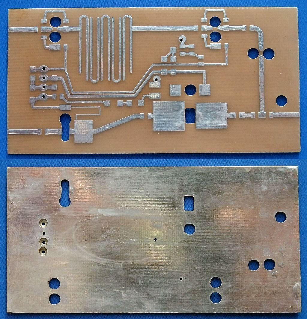
The RF front end for 3.4GHz includes a band-pass filter sensitive to substrate tolerances:
After etching and drilling, copper is removed in the ground plane around signal-carrying holes and both sides of the board are tinned using additional flux:
Before installing any components, the grounding holes have to be covered with 0.1mm-thick tinned copper tape. A suitable piece of 0.2mm thick tinned copper sheet has to be soldered in place to spread the heat produced by the ALM32320 GaAs HEMT hybrid:
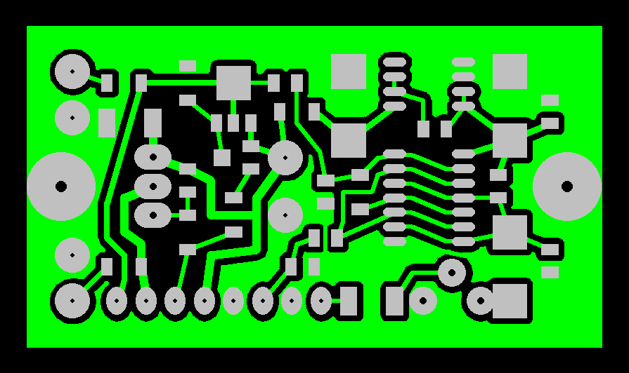
The Costas demodulator is built on a single-sided printed-circuit board:
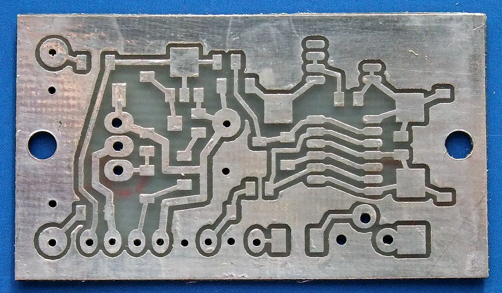
After etching and drilling, the board is tinned using additional flux:
The RX/TX switch is built on a single-sided printed-circuit board:
After etching and drilling, the board is tinned using additional flux:
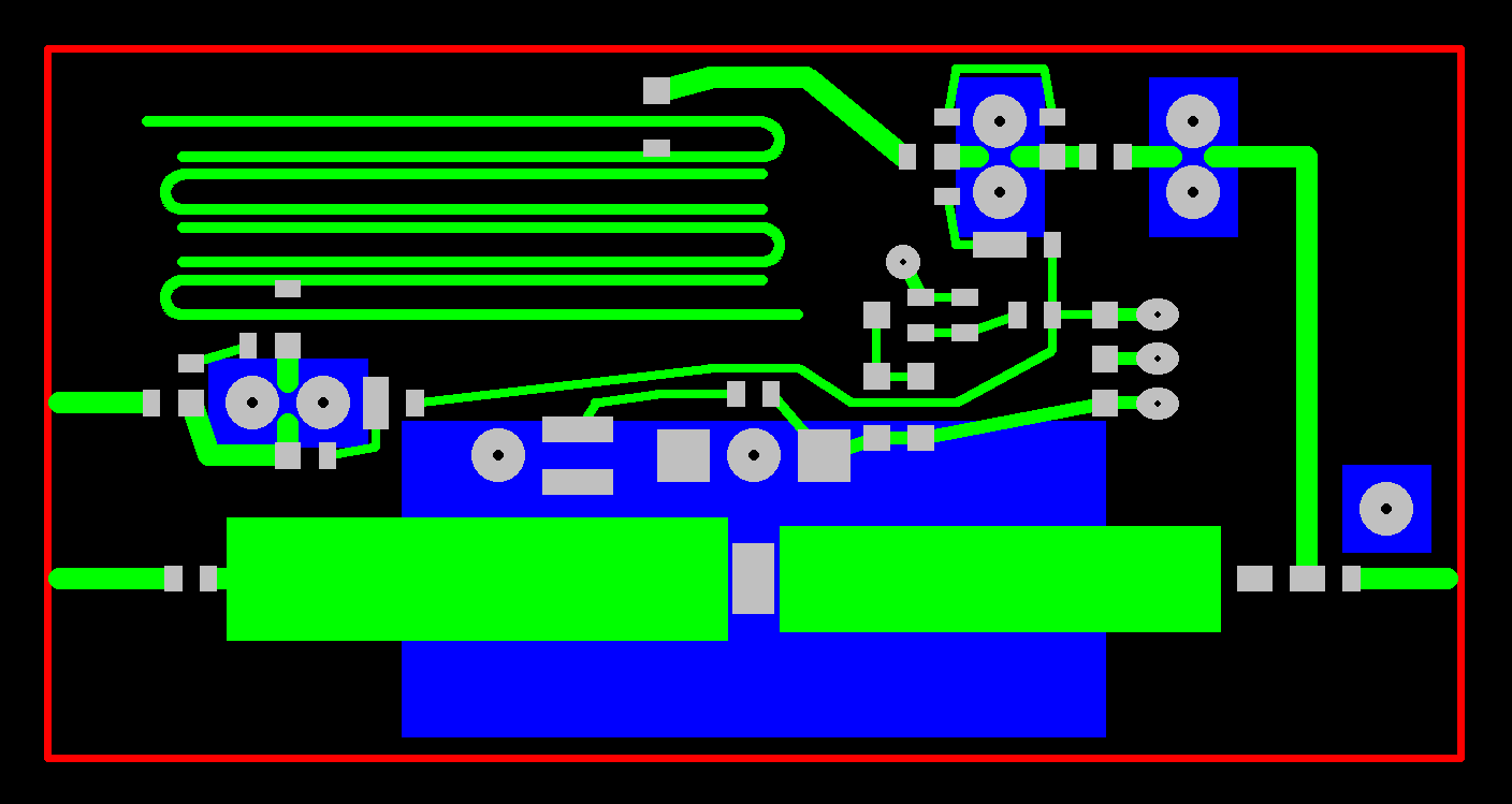
The linear regulator is built on a single-sided printed-circuit board:
After etching and drilling, the board is tinned using additional flux:
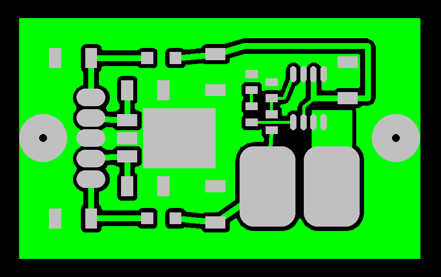
The switching regulator is built on a single-sided printed-circuit board:
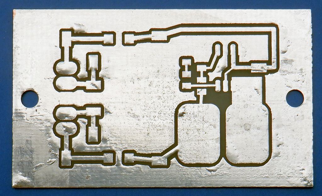
After etching and drilling, the board is tinned using additional flux:
(DESIGN) (COSTAS) (FRONTEND) (SUPPLY) (PCB) (SHIELD) (ASSEMBLY) (TEST) (HOME)