(DESIGN)
(COSTAS)
(FRONTEND)
(SUPPLY)
(PCB)
(SHIELD)
(ASSEMBLY)
(TEST)
(HOME)
10Mbps BPSK ZIF transceivers for 1.2GHz, 2.3GHz and 3.4GHz
Matjaz Vidmar, S53MV
1. Transceiver design
An efficient replacement for the obsolete AX.25 protocol is the NBP or Ne-Brezhibni Protokol (Non-Flawless Protocol). Using simplex BPSK radios operating at 1.2Mbps, 2Mbps and/or 10Mbps in the lower microwave frequency bands NBP is able to achieve a useful throughput of up to 80% of the simplex channel data rate (8Mbps download or upload with 10Mbps radios) in links spanning distances beyond 100km with small-size antennas. Unfortunately, the BPSK radios used for NBP were not simple to build, including large amounts of discrete components, several modules and complex shielding requirements.
NBP started in 2010 with 1.2Mbps BPSK radios used in heritage AX.25 links from 1995 onward. The 1.2Mbps radios were soon modified for 2Mbps NBP. The first 10Mbps links with NBPv2 used transverters for 2.3GHz and 3.4GHz together with 400MHz IF radios. A much better solution was the 23cm BPSK RTX za 10Mbit/s (SLO - 23cm BPSK RTX for 10Mbit/s NBP packet-radio), much simpler than transverters but still requiring several discrete components.
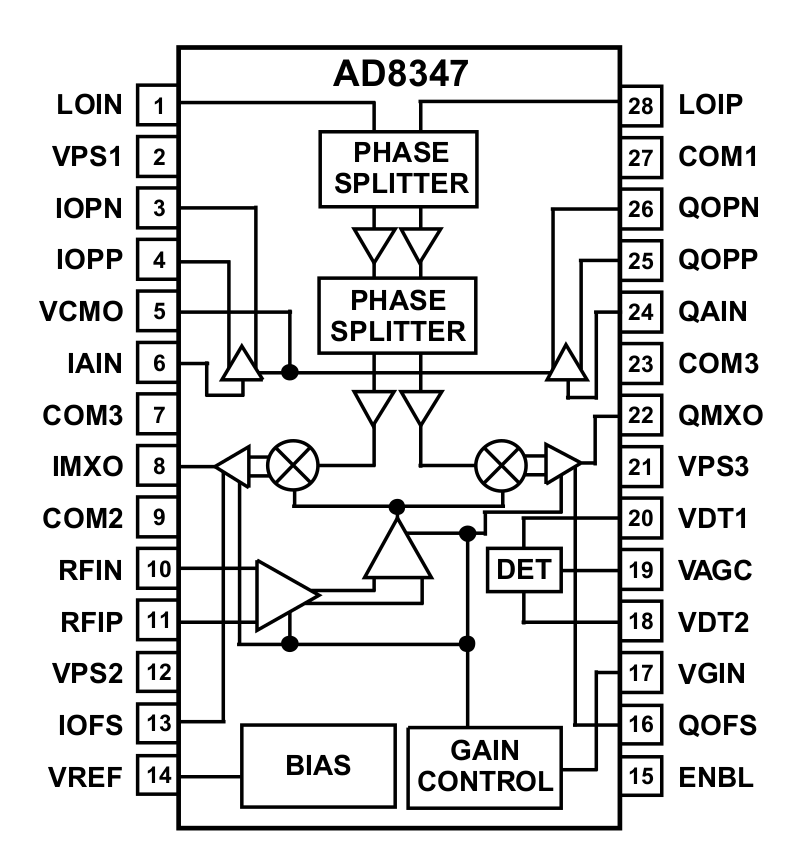
Today most available transceiver chips are highly integrated components for the 802.11 family of WiFi standards. The latter mandate the power-inefficient OFDM modulation not suitable for long-reach links. Fortunately some intermediate, more flexible solutions are available. The 10Mbps BPSK ZIF transceivers for 1.2GHz, 2.3GHz and 3.4GHz to be described in this article are all based on the AD8347 Zero-Intermediate-Frequency receiver chip. The AD8347 includes an RF amplifier with AGC, a quadrature mixer including a LO phase splitter and a two channel I-Q Zero-IF amplifier, officially covering the frequency band from 0.8GHz to 2.7GHz:
A receiver with the AD8347 can be optimized for BPSK operation at both 10Mbps NBPv2 as well as the original 2Mbps NBP (component values in parentheses). The differences are in the signal and AGC filters:

The quadrature ZIF outputs I, /I, Q and /Q of the AD8347 carry all of the information in the processed bandwidth. The actual modulation depends on the following Costas-loop demodulator. At 1.2GHz and 2.3GHz, inside the specified frequency range of the AD8347, the unwanted crosstalk of the local oscillator can be eliminated using AC coupling as defined with the capacitors on pins IOFS and QOFS. The 6.8nF capacitors provide a low-frequency cutoff of about 6kHz suitable for 10Mbps BPSK. Alternatively 22nF capacitors provide a low-frequency cutoff of about 2kHz suitable for 2Mbps operation.
At 3.4GHz, beyond the guaranteed frequency range, both gain and quadrature of the AD8347 remain excellent. Unfortunately the unwanted LO crosstalk is much worse and requires an additional lead-lag network [parentheses] with a additional 6.8nF capacitor and the already present 4.7kohm resistor to stabilize the AGC feedback.
The AD8347 requires about 60mA at a single supply voltage of 3.3V, much less than comparable discrete solutions. The AGC feedback is selected for a higher output of about 800mVpp as required by the following BPSK digital Costas-loop demodulator. Unfortunately the AD8347 has much RF gain and little Zero-IF gain to mitigate the LO crosstalk. This is a common design limitation of many Zero-IF chips, including WiFi and other chips. A higher Zero-IF output requires additional RF gain in the receiver further reducing the dynamic range of the receiver.
The unwanted LO crosstalk of the AD8347 can be reduced by using a differential LO signal as provided by many popular PLL frequency synthesizer chips, including the ADF4351 and the MAX2870. Both are fractional PLLs and can generate almost any frequency in the required range:
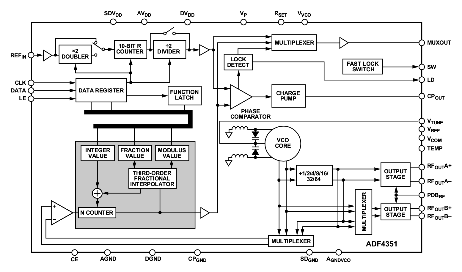
Although not as sensitive as OFDM, even simple digital modulations like BPSK are rather sensitive to carrier-frequency errors. It therefore makes sense to drive the PLL chip with a 32MHz TCXO reference oscillator providing a frequency accuracy in the 1ppm range. The many internal registers of the ADF4351 are programmed by a small PIC12F675 microcontroller through three lines DATA, CLK and LE:

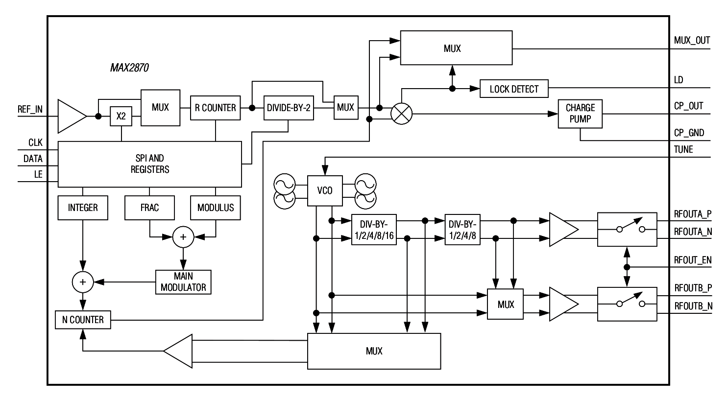
The MAX2870 frequency synthesizer is pin compatible to the ADF4351. Of course the values of some components are different as well as the values to be programmed into the many internal registers of the MAX2870:

The PIC12F675 runs independently on its internal RC clock. The practical circuit uses the 8-pin DIL version installed on a socket so that new channels can be simply implemented by replacing the micorcontroller chip. The current microcontroller firmware (picsw.zip) allows the selection of 5 preprogrammed frequency channels through the application of a DC voltage on the input AN3 of the built-in A/D converter. The circuit is designed for single wire to the channel selector switching among open, 15kohm, 4.7kohm, 1.5kohm or direct short to ground.
The PLL register set is programmed twice for reliable operation at power-on and on every frequency change. Further, a watchdog timer will trigger additional register programming about every 15 minutes, depending on the exact RC clock of the PIC12F675. Finally, the PLL registers will be programmed again if the MUXOUT signals an unlock. Every time the PLL registers are programmed (twice), the TEST output GP5 changes state.
There are three different versions of the firmware for the 1.2GHz, 2.3GHz and 3.4GHz radios. Of course there are two different versions of each firmware for the ADF4351 and MAX2870 chips. Depending on the programmed frequency and output signal level, the current drain of the PLL chip changes, but it stays in the 100mA range at 3.3V supply.
Any balanced mixer may perform as a BPSK modulator. In order to remain compatible with the ZIF-receiver and PLL-synthesizer chips as well as reduce LO crosstalk, it makes sense to use the AD8349 quadrature modulator chip in spite of its high current drain in excess of 100mA at 5V:
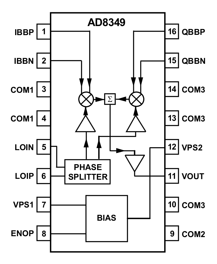
Of course both I and Q inputs of the AD8349 quadrature modulator are driven in parallel for BPSK operation. The BC857 PNP transistors are used for DC level shift. A GALI5 MMIC is used to boost the output power to about +18dBm ant 1.2GHz or +15dBm at 2.3GHz:

Although the operation of the AD8349 is guaranteed from 0.7GHz to 2.7GHz, the chip provides a rather low but useful output at 3.4GHz. Both the output power and unwanted crosstalk can be improved by different resistor values in the PLL-output-power splitter. Replacing the MMIC with a GALI52 and some additional components as indicated in [parentheses], about +9dBm of BPSK signal can be obtained at 3.4GHz.
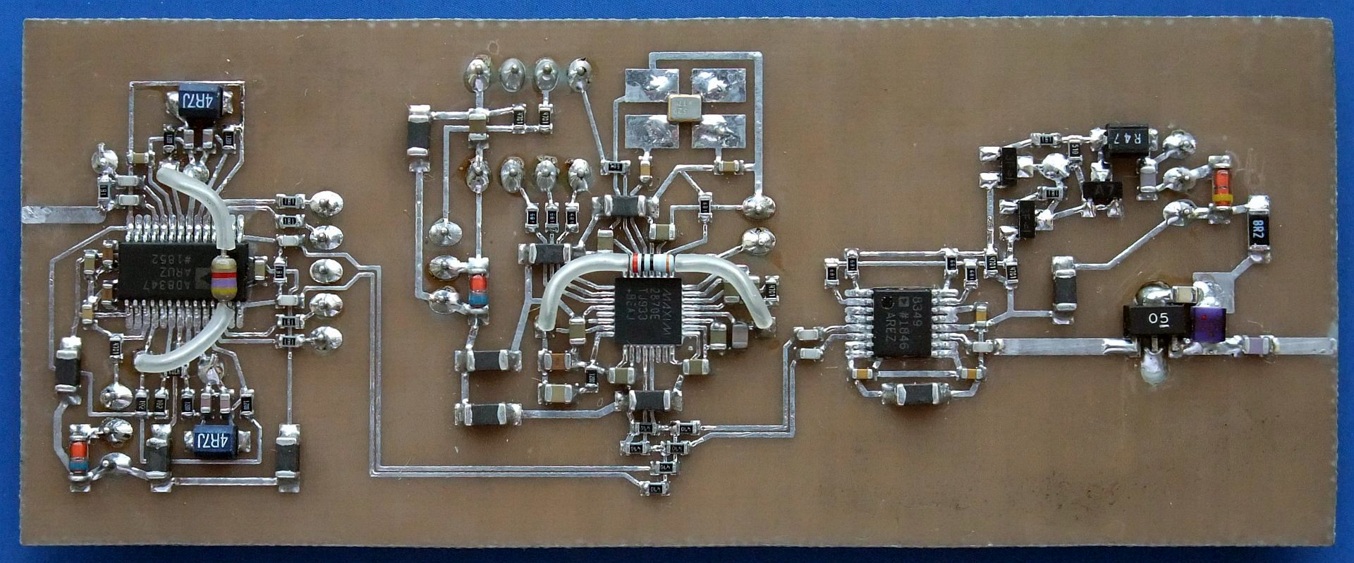
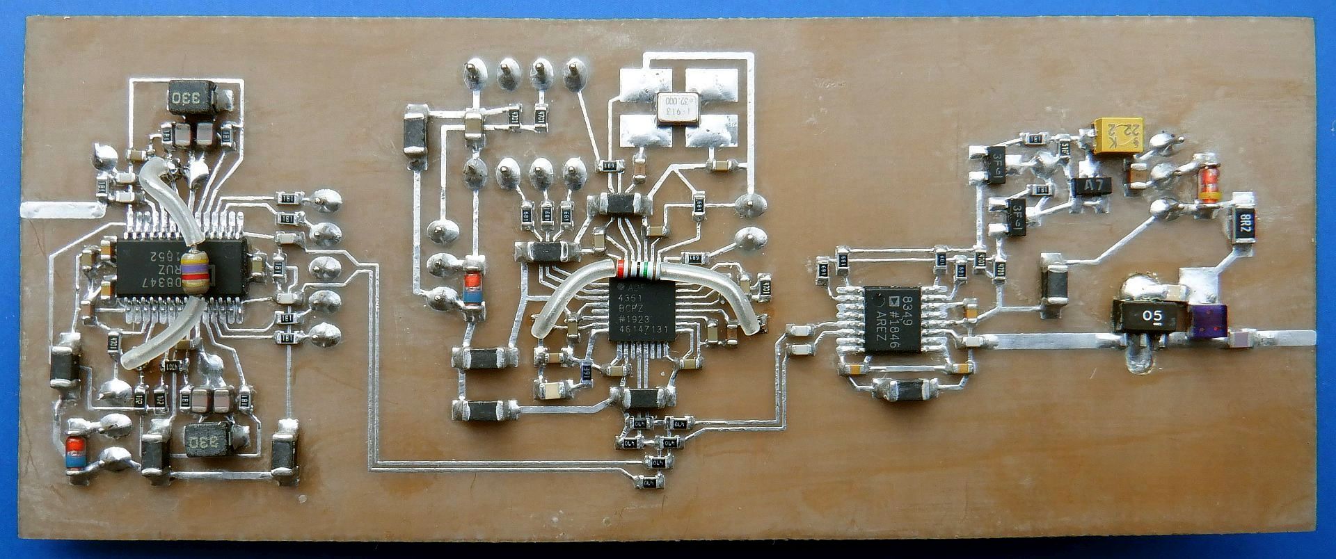
All three circuits, ZIF receiver, PLL synthesizer and BPSK modulator are assembled on a single double-sided printed-circuit board. One side of the board carries most of the electronic compunents while the other side acts as a ground plane. 50ohm microstrip lines are only used on the receiver input and on the modulator output.
The 10Mbps version with a MAX2870 synthesizer is shown on the following photo:
The 2Mbps version with an ADF4351 synthesizer is similar:
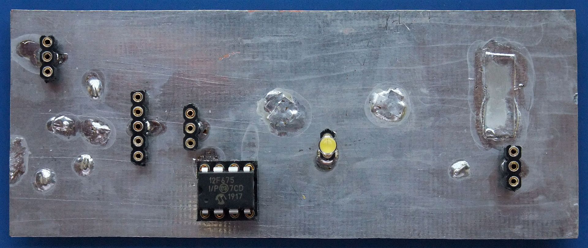
The ground-plane side only carries supply and low frequency connectors, the PIC12F675 microcontroller and the lock LED:
The described module including the ZIF receiver, PLL synthesizer and BPSK modulator is able to cover the whole frequency range from less than 1GHz up to at least 2.5GHz by just programming the PLL. Adjusting the values of some components the same circuit may operate even at 3.4GHz. Of course the ZIF receiver requires a LNA and band-pass filter on its input and a Costas-loop demodulator on its output. The BPSK modulator requires an RF power amplifier and antenna switch. Finally all of the circuits require different supply voltages, some of them switched between reception and transmission. All required circuits will be described in the following sections of this article.
(DESIGN) (COSTAS) (FRONTEND) (SUPPLY) (PCB) (SHIELD) (ASSEMBLY) (TEST) (HOME)