Contents
- 1 Introducing the participants
- 1.1 A couple of Trimble 65256 OCXOs
- 1.2 A Bliley NV47M1008 OCXO
- 1.3 A couple of Epson Toyocom TCO-6920N DOCXOs
- 1.4 A bunch of CTI OSC5A2B02 OCXOs
- 1.5 A couple of HP10811-60111 OCXOs
- 1.6 A couple of Trimble 57963-C GPSDOs
- 1.7 A CellSync 1100 GPSDO
- 1.8 My own GPSDO design (the MBSD)
- 1.9 A TEMEX LPFRS-01 rubidium controlled oscillator
- 1.10 A couple of borrowed HP5350 counters
- 1.11 A borrowed Oscilloquartz OSA 4350 GPSDO
- 1.12 A borrowed Quartzlock E8-X GPSDO
- 1.13 A borrowed Lucent RFG-RB rubidium controlled oscillator
- 1.14 A borrowed EGG timer
- 1.15 Three PTI XO5051-001 100MHz OCXOs
- 1.16 Four HP E1938 OCXOs
- 1.17 Two LPRO rubidium boxes
- 1.18 A HP Z3805A GPSDO
- 1.19 My HP8663 signal generator
- 2 What and how it was measured
- 3 Measurements of phase noise
- 3.1 HP10811
- 3.2 Epson Toyocom TCO-6920
- 3.3 Trimble 65256 OCXO
- 3.4 Bliley NV47M1008
- 3.5 EGG H314 OCXO
- 3.6 CTI OSC5A2B02
- 3.7 The RFG-RB rubidium
- 3.8 The LPFRS rubidiums
- 3.9 Trimble 57963-C GPSDO
- 3.10 Oscilloquartz OSA 4350 GPSDO
- 3.11 Quartzlock E8X GPSDO
- 3.12 CellSync 1100 GPSDO
- 3.13 PTI 100MHz
- 4 Measurements of frequency stability
- 4.1 The rubidiums
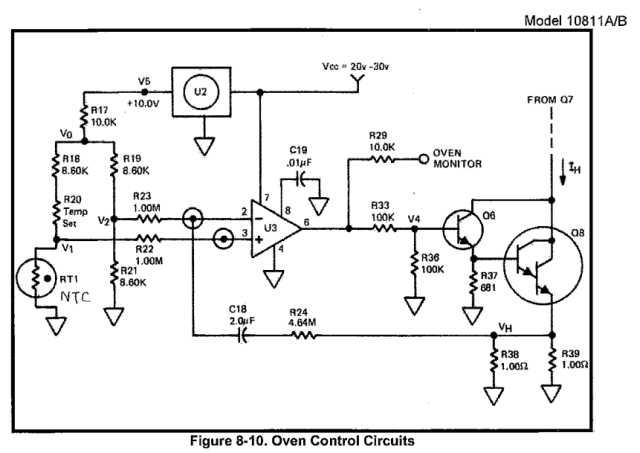
- 4.2 HP10811 (& thermostat repair)
- 4.3 Epson Toyocom TCO-6920
- 4.4 Trimble 65256
- 4.5 Bliley NV47M1008
- 4.6 CTI OSC5A2B02
- 4.7 Trimble 57963-C GPSDO + common antenna test
- 4.8 Oscilloquartz OSA 4350 GPSDO
- 4.9 Quartzlock E8X GPSDO
- 4.10 CellSync 1100 GPSDO
- 4.11 PTI 100MHz
- 4.12 HP E1938
- 5 Conclusions
1 Introducing the participants
All of the participants are elderly citizens, with a lot of work years behind them, so maybe what I measured, is not a fair representation of what they were capable of, in the blossom of their youth.
Also, there seems to be a consensus, that you must let these guys run for at least a month, to truly stabilize. I must admit, that I did not do that, typical warm up times were between one and a few days.
The measuremets presented here were not done in a tightly climatically controlled vault 20m below ground, but in a room with people walking around, opening doors, etc. They respresent more how these oscillators behave in a typycal hobbyist's garage lab - I think that is probably more interesting for the majority of readers anyway. It was not my intention to scale the lofty heights of time nuttery here, but just to see, what can be done with cheap, widely available stuff, in a typical ham shack environment.
I thought about including some new OCXOs, so I did a search for "OCXO" on Farnell. It brought up about 75 hits, with prices from 31.12 to 1226.00 euros. I checked a few datasheets, but even the most expensive ones were only about as good as my old clunkers, so I didn't bother, and saved some money.
Well, there are the Ocilloquartz BVA and Vectron OX series, but these are neither cheap nor easy to find.
1.1 A couple of Trimble 65256 OCXOs
Bought from .... on Ebay. #1 has date code 0640 and #2 0918. They definitely show some wear and tear, but otherwise seem to work well. I mounted them on small protoboards, with some supply filtering, an TL431 5V tuning voltage stabilizer and tuning potentiometer.
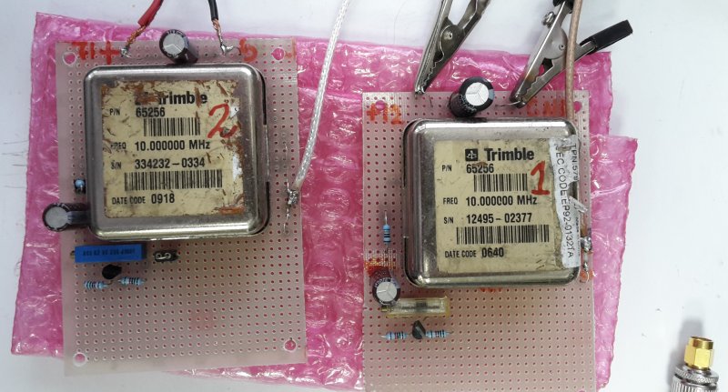
Fig 1.1.1 A couple of Trimble OCXOs on proto boards
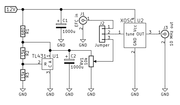
Fig 1.1.2 Schematic of the OCXO test board
I could find no datasheet about these oscillators online.
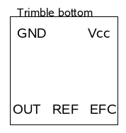
Fig 1.1.3 Trimble OCXO pinout (bottom view) EFC=VCO input, REF = ?
There are rumors, that both 12V and 5V variants exist out there, with the same type number (!!). After running both of them on 12V for many days, I noticed that #2 got noticeably hotter, thermal camera measured 54C on the top label vs 46C on #1, at 22C ambient. #2 also drew slightly more current, 270 vs 200mA. I decided to investigate.
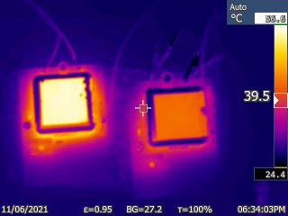
Fig 1.1.4 Thermal image of the two trimble OCXOs
#1 starts oscillating at about 5.5V (5.7V with slowly rising voltage), and going down with the voltage, the unloaded output amplitude (4.0Vpp sine wave) starts to decrease at 5.7V.
#2 starts at 3.5V (4.5V with slowly rising voltage), and going down with the voltage, the unloaded output amplitude (4.0Vpp) starts to diminish at 3.5V.
Hmmmm. #1 is almost certainly not a 5V type, but #2 could be? When run at 5V, it still heats to 54C and draws 600mA.
On cold start, the 5V type draws more than 1.5A (power supply current limit), and the 12V type 600mA. After warm up, the 5V type draws 600mA at 5V and 270mA at 12V. The 12V type stabilizes at about 200mA, all at 22C ambient, free air (no fans, heatsinks or added thermal insulation).
Later I got two more OCXOs of the same type, on the Trimble GPSDO boards, date codes 1410 and 1543. They are certainly 5V types, as the board's supply is 5.5V, and I see no voltage converters on the boards. They both reach 54C on the label, and I did not desolder them, to measure the current. The boards draw a bit more than 600mA, this computes.
So, does #1 (the 12V type) just have a faulty thermostat? Squirted freeze spray, current rose, hit it with a hair dryer, current fell, the thermostat seems to work OK. Could it be, that when they went 5V, they also changed the temperature set point? Or maybe just started to skimp on thermal insulation? Can't tell, since I only have one 12V specimen.
Tuning sensitivity is about 1.6 ... 1.7 Hz/V on both. Supply pull is less than 100uHz/V, after a couple of minutes for the thermostat to "come back".
Both have 3.6Vpp output open, and 1.8Vpp into 50Ohm, no DC.
The most important thing learned here is, that the 5V type will survive for days on 12V - well, at least the one that I have did :-)
Still later, I read on the web that these cans contain another can - usually a Vectron OCXO. So I opened the cans:
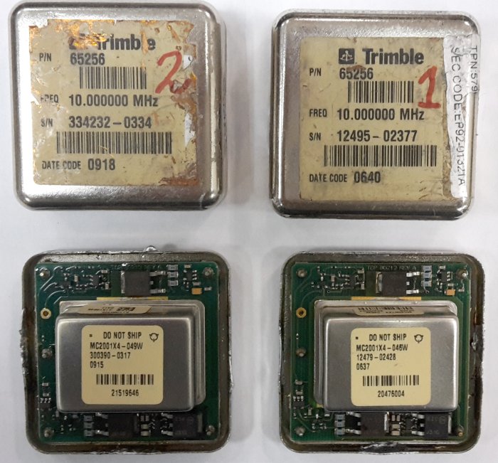
Fig 1.1.5
The internal "do not ship" cans are MC2001X4-046W in the 12V type, and MC2001X4-049W in the 5V type. These are Corning/Vectron OCXOs, quite obsolete, could find no datasheet on the web.
On the PCB, there are two ON semiconductor J210G mosfets, an J31G bipolar, some SOT-23 and SOT23-5 packages, etc. Looks like another thermostat, so I guess these may be double ovens?
Up to table of contents
1.2 A Bliley NV47M1008 OCXO
Bought from .... on Ebay. Arrived with a very scruffy label, but othervise no visible damage, except for some beauty marks. Looks like it has mingled with some screws and other hardware at some place.
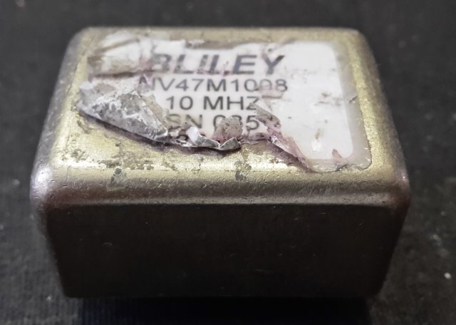
Fig 1.2.1
Found a datasheet on the web, but could not determine from it, what the supply voltage for this type should be. So, I hooked a scope, and slowly increased the supply. It started to oscillate at 2.4V, with full amplituce (CMOS) square wave.
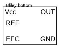
Fig 1.2.2 Bliley OCXO pinout (bottom view) EFC=VCO input, REF = 4V output
There is a "V REF" pin on the can. At lower supply voltages it tracks the supply voltage, but remains fixed at 4V as the supply passes 4V. I guess this is a stabilized output for a frequency setting potentioneter. I went up to 6V, which is still safe for HCMOS, and it stayed at 4V. From this, I think 5V is the right supply.
On cold start it draws about 500mA, after warm up about 180, at 22C ambient, free air. The top label reaches about 45C.
Tuning slope is 11.4 Hz/V. Output 4Vpp CMOS like square, 50 ohm loaded 2.5Vpp (0...2.5V, 1.25V average DC) square.
Up to table of contents
1.3 A couple of Epson Toyocom TCO-6920N DOCXOs
Bought from .... on Ebay. Advertised as double oven, datasheet also mentions that.
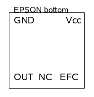
Fig 1.3.1 Epson OCXO pinout (bottom view) EFC=VCO input
These are 12V types, start oscillating at 5.5V, the amplitude reaches full 2Vpp sine wawe (no load) at 10V supply.
Fig 1.3.2 Which date??
The case temperature, after warm up, is 55 and 53 degrees, at 25C ambient, with current consumption batween 180 and 190mA. Cold start, they suck a little less than an amp, for about three minutes, then reach equilibrium after maybe 15 minutes.
The tuning sensitivity is about 0.75Hz/V.
The output is 2Vpp sine, can drive 50 ohm with a 1.6Vpp sine, no DC.
Up to table of contents
1.4 A bunch of CTI OSC5A2B02 OCXOs
Bought from .... on Ebay. Got a dozen for less than a single one of the others. Found a datasheet, it is in chinese, but with english anotation. At least no doubt that this is a 5V device.
Fig 1.4.1
Draws about 350mA on cold start, 200mA after warm up. Top of the case around 57C. Tuning slope is around 10Hz/V.
The output is a 4Vpp CMOS-like square wave. Loading it with 50 ohm, reduces amplitude to 2Vpp (0...2V, 1V average DC).
Fig 1.4.2 CTI OCXO pinout (bottom view) EFC=VCO input
Since I had a dozen of these, I decided to cut one open, and see what is inside
Fig 1.4.3 I ripped one component off, while sawing the case. I did no soldering here, flux residues are 100% original
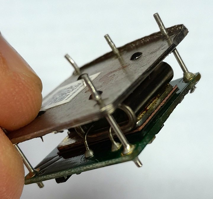
Fig 1.4.4 Thermal insulation is quite thin
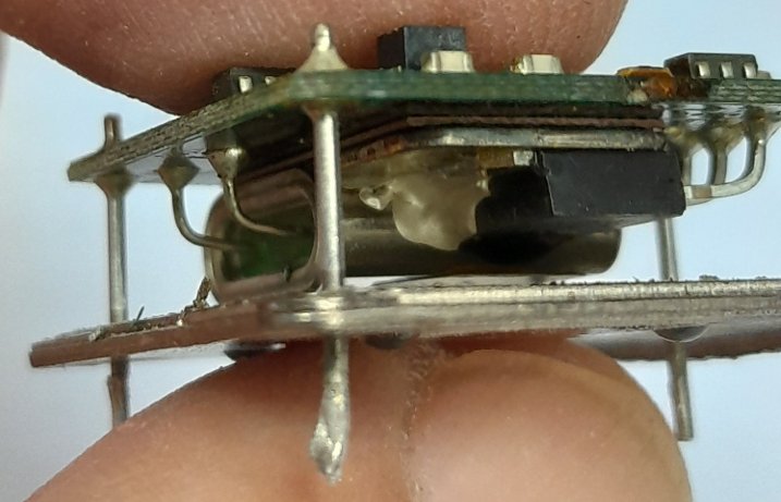
Fig 1.4.5 One transistor for heating, thermistor is in the goo (I guess)
Up to table of contents
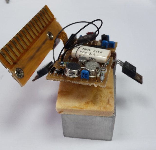
1.5 A couple of HP10811-60111 OCXOs
Bought from .... on Ebay. At first glance, they looked in mint condition, maybe NOS, but later I found a burn mark (some soot and a melted point) on the bottom edge of one. Looks like it encountered some high current source. But it works well, so this must have been a platonic affair only, no penetration.
UPDATE: Later I found that things may not have been that inocent, see below, the frequency stability measurements. The bruised one is refered to as #2.
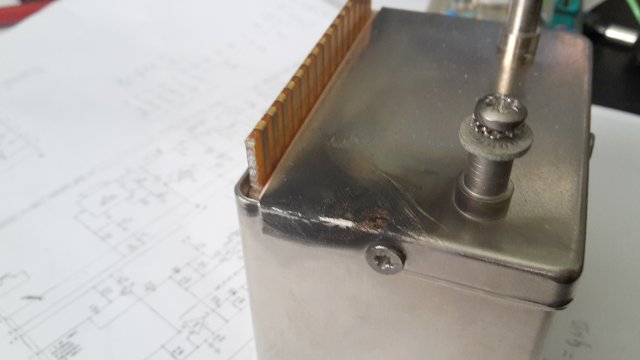
Fig 1.5.1
A very good and exhaustive manual from HP can be found on the web, so no hide and seek games with these.
The OCXOs came mounted on small printed circuit boards, with some chips and stuff. More web searching, and I found out that these OCXOs are (were) used in many HP counters, like HP5328, whose service manual can also be found online. There I could find the schematic of this "oscillator support" board.
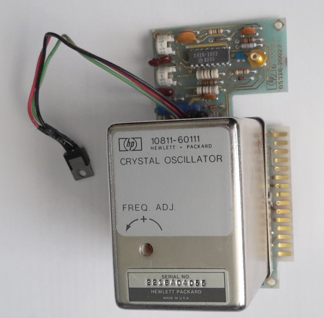
Fig 1.5.2
This board contains several things: an 723 based 12V regulator for the oscillator, a shaper, detector and automatic switch over circuit for an external reference input, a divider by 10 for an 1MHz output, and a 5V regulator, in the form of a TO220 package dangling on colored wires, for the TTL chips.
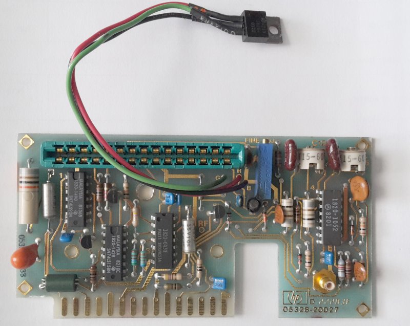
Fig 1.5.3
The board runs on a 20V supply, and -5V for the ECL stuff in the external clock circuits.
BTW, the green edge connector is EDAC 305-030-521-501, Mouser has them in stock.
This OCXO is different from the others described here, in that it has separate power supplies for the heater and oscillator. This is nice, because you need a precision supply only for the small oscillator current.
These are also the only ones having a mechanical tuning facility.
The electrical tuning sensitivity is about -0.35Hz/V. It is negative, because the varicap cathode is connencted to an internal 6V bias point. The EFC range is -5V to 5V.
I decided I only need the 723 based 12V regulator, and the frequency setting potentiometer, so I unsoldered all of the chips except the 723 (marked 1820-0439).
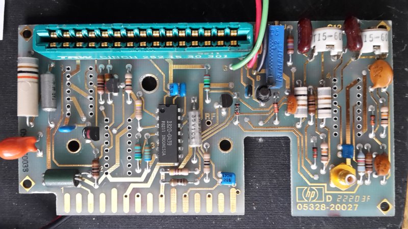
Fig 1.5.4
The output was originally buffered through an emitter follower, but with a 1k emitor resistor it wasn't able to drive 50 ohm. In fact, the distortion was so bad, that my HP3048 refused to measure phase noise. Therefore, I also removed the transistor and the bias resistors, and wired the OCXO's output directly to the SMB connector on the board. It can drive 1.5Vpp (16.6 dBm) sine into 50 ohm, no DC component.
Since there are no more 5V TTL chips on the board, we can get rid of the dangling 5V regulator too.
I had no suitable edge connector, so I just soldered two wires to suitable pads, to power the board:
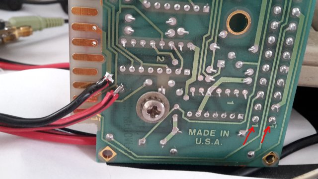
Fig 1.5.5
Red wire is plus 20V. Pins 1 (OCXO ground) and 7 (board ground) on the board edge connector must be connected together. Red arrows mark the 10 MHz output from the HP10811, the two pins are connected together on the board.
While the edge connectors on the oscillator and on the support board are of the same type, the pinout is completely different!
The pinout on the OCXO can (NOT the suport board) is this:
Pin1    RF output 10MHz
Pin2    RF output ground
Pin3    Oscillator supply, +11.0 to +13.5V
Pin4    Oscillator supply ground
Pin5    EFC ground
Pin6    EFC
Pins 7...10   NC
Pin11   Oven monitor output
Pins 12,13    NC
Pin14   Oven supply, +20 to +30V
Pin16   Oven supply ground
Pins 2,4,5 are internally connected together. Contacts on both sides are connected together.
To have three similar ocillators for the "triangular hat" phase noise measurement, I later bought a third HP10811, this time a "D" type (HP10811-60120). It is later referenced as "#3".
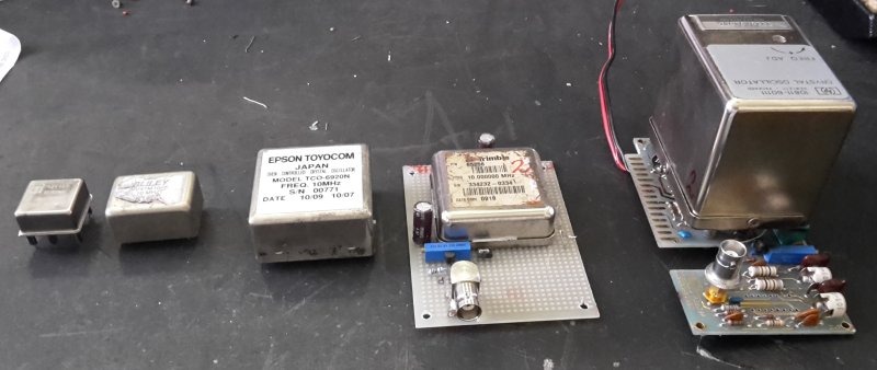
Fig 1.5.6
A lineup of OCXOs, to show relative size. From left to right: CTI, Bliley, Epson, Trimble, HP.
Up to table of contents
1.6 A couple of Trimble 57963-C GPSDOs
Bought from .... on Ebay. Kudos to the seller, for including a short piece of 50 wire fine pitch flat cable, and a small breakout board, otherwise it would be quite a messy job, connecting to the board.
These boards are quite complex, a lot of stuff on both sides:
Fig 1.6.1
Fig 1.6.2
Chips top: XEMICS 3330R GPS RF front end, Xilinx XC3950 FPGA, TI TMS320VC5509AZHH DSP, SST 343248, MAX3232, LT1764A.
Chips bottom: ACT174, ACT374, two MAX1241 12bit A/D, TL16C752 dual UART, Kyinyx KY32-464WP, and then some small SMD 5 and 6 pin packages, probably opamps, etc.
I made a small chassis to mount both boards and hold some front panel connectors. Bought a bunch of Chinese MCX to SMA pigtails, to have SMA connectors on the front panel. (1PPS is not wired in the photo below)
Fig 1.6.3
I also included a LM1084-ADJ regulator, to make the required 5.5V supply, mounted on the bottom (not visible), to use my universal 12V supply voltage.
The fat chip next to the flat connector is a MAX3232, making the serial port a "true" RS232, with bipolar levels, so beware!
Up to table of contents
1.7 A CellSync 1100 GPSDO
I bought this box in 2001 at a surplus store in Silicon Valley. I was not able to get any data about it. When I connect the antenna, after a few minutes, it goes into "blinking green" mode, not sure what that means. I thought it was doing the survey, but after one week it is still blinking. Later I saw the Trimble units go into "blinking green", when fully locked, so all might be well here too (I hope).
Fig 1.7.1
It has a bunch of serial ports, but none of them wants to talk with me - or with lady Heather, for that matter.
Inside the box, there is A LOT of stuff.
Fig 1.7.2
A higher resolution image is here. The OCXO is covered in foam for additional thermal insulation. Under the foam block is an Vectron CO-766Y4223 20 MHz oscillator. Could not find any datasheet, probably too old.
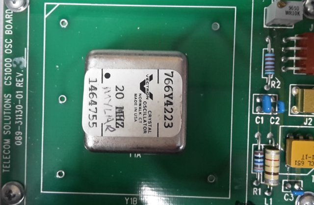
Fig 1.7.3
The OCXO board has an "universal" layout, that can also accomodate the bigger OCXOs, like the Trimble and Epson types described above.
Up to table of contents
1.8 My own GPSDO design, the MBSD
I found the commercial GPSDO designs described here not very suitable for my interferometric purposes, so I decided to try my hand at GPSDO design. More about that here.
1.9 A TEMEX LPFRS-01 rubidium controlled oscillator
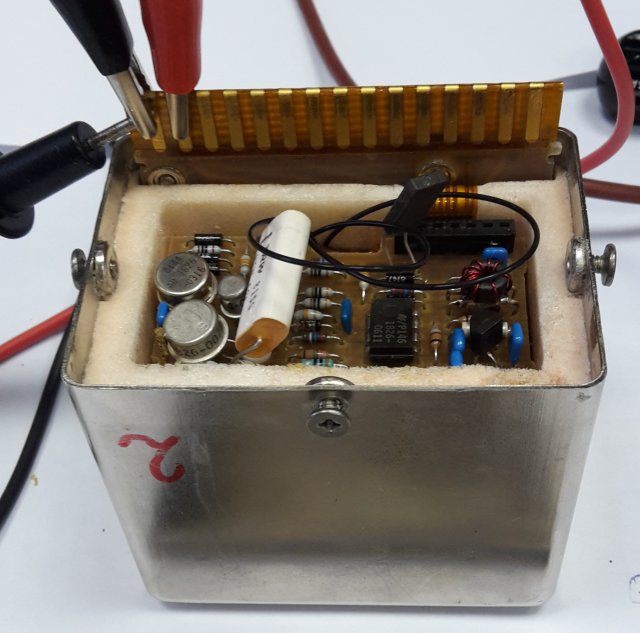
Bought from .... on Ebay. The LPFRS unit came mounted on a heatsink, with a small circuit board, to match the old LPRO format in size and connector.
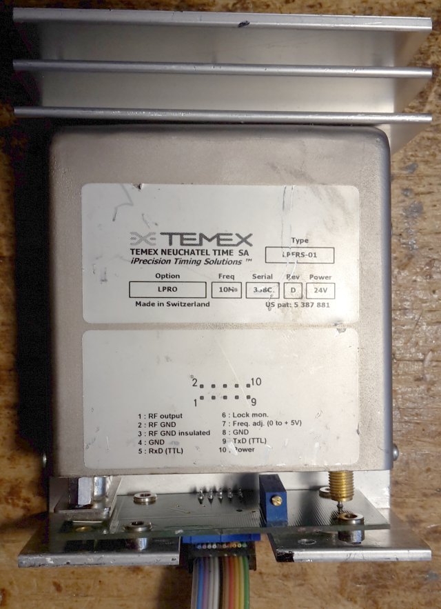
Fig 1.9.1
It looked very nice, until I saw this horror:
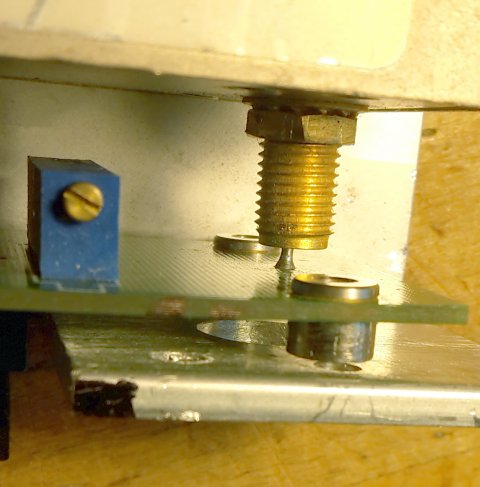
Fig 1.9.2
This really badly hurt my RF feelings, so I had to do something. I drilled some additional holes into the heatsink, and cut the board close to the trimpot
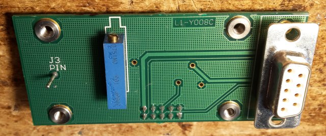
Fig 1.9.3
to remove that phallic monster and make a decent RF connection.
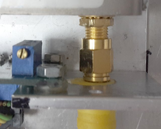
Fig 1.9.4
Then I powered it up, and connected lady Heather to decode the status messages on the serial line. The LPFRS contains a microcontroller, which can communicate with the external world throgh a serial port. The numbers look a bit end-of-life-ish, but the output is still OK. On the web, mostly on forums, I found a lot of posts about people restoring their rubidiums, of this and similar types, by changing the caps, heating the lamp, tweaking the trimmers, etc. So I hope I can keep it running for some time.
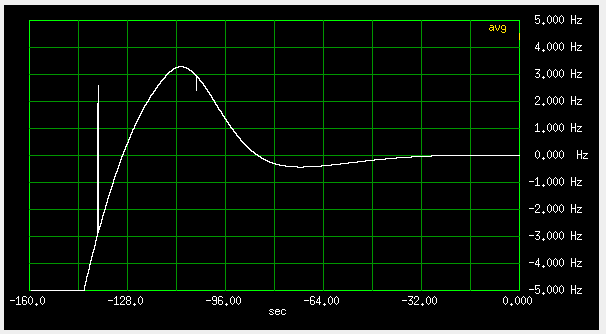
I wrote a small program to draw the reported values versus time. The next figure shows behavior upon power up:
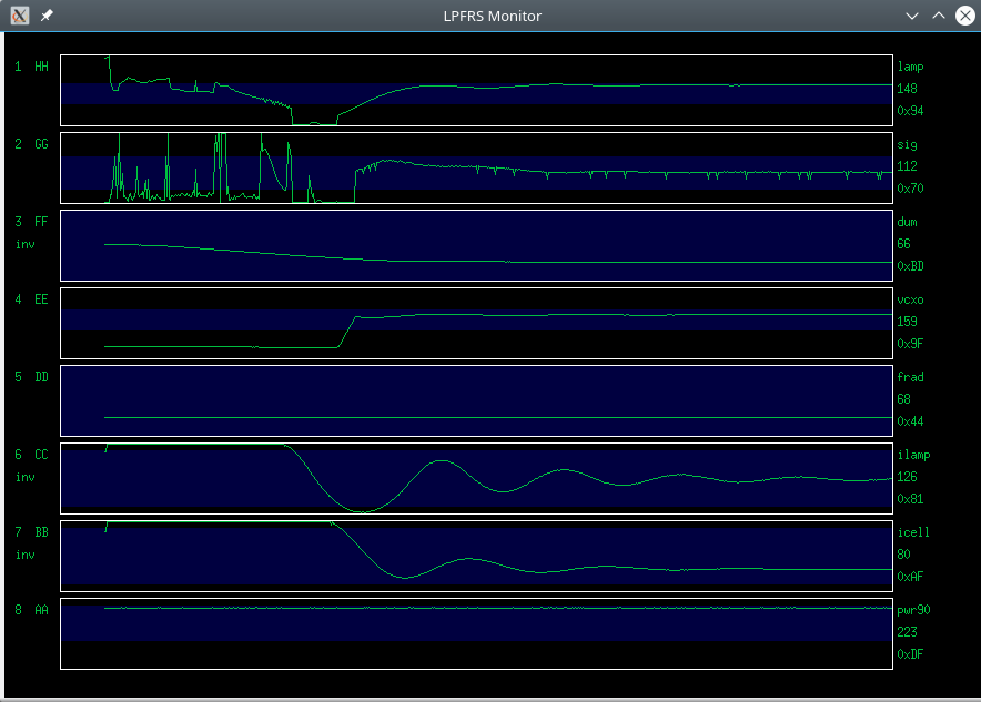
Fig 1.9.5
Top graph is the lamp voltage. It seems high, but the lamp values from the lpfrs come inverted, so the lamp is just still good enough.
Graphs 6 and 7 are the heater current of the lamp and absorption cells, showing a low damping of the thermostat control loops.
Finally, I mounted it on a chassis, together with a 24V transformer, rectifier and a 7824. The small blue board is a serial/USB adapter.
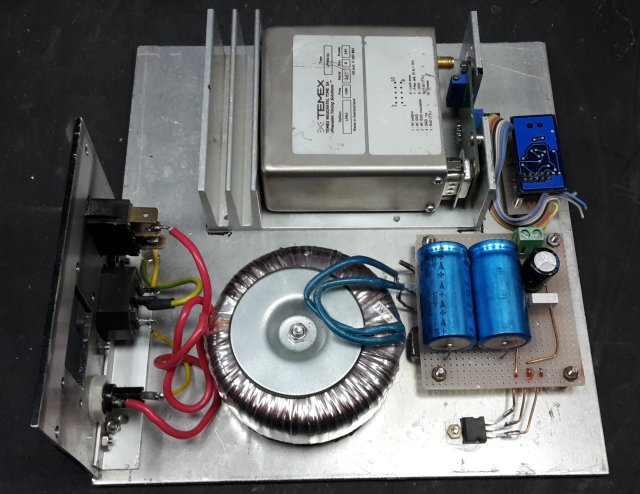
Fig 1.9.6
Later I bought two more LPFRSs, sold as "not locked". I managed to get them working, more about that is here.
Up to table of contents
1.10 A couple of borrowed HP5350 counters
I borrowed these before I had my HP10811 ocillators. In fact, they contain exactly the same type HP10811-60111 OCXOs, as described above, but on a different board. They have a BNC 10 MHz reference output on the backside, which I could use.
Fig 1.10.1
I later used these to see how much sitting in a big metal box with a quality power supply would help. My other HP10811s just sat on the desktop, power supplied via banana leads from an old lab supply.
Up to table of contents
1.11 A borrowed Oscilloquartz OSA 4530 GPSDO
I borrowed this to see how a Swiss big-name professional non-junkyard GPSDO behaves.
Fig 1.11.1
Up to table of contents
1.12 A borrowed Quatzlock E8-X GPSDO
A friend bought this one, and I borrowed it for measurements. It costs more than 1000 euros, more than all of the other non-borrowed items described here together.
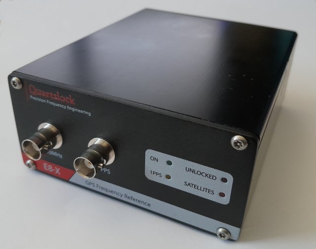
Fig 1.12.1
Up to table of contents
1.13 A borrowed Lucent RFG-RB rubidium controlled oscillator
I wanted to try rubidium vs rubidium, so I borrowed one. I want to buy a second one, but I came too late to the game, and Ebay prices are now rather crazy.
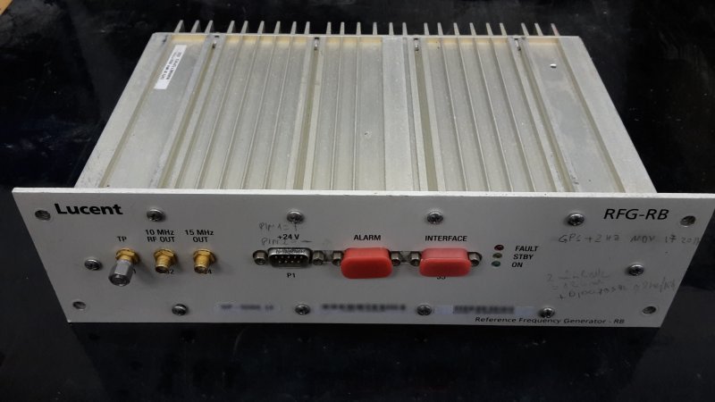
Fig 1.13.1
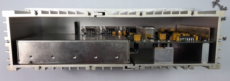
Fig 1.13.2
Inside is an EFRATOM model SLCR-101 (pn 104796-001) box, which has no microcontroller, to report the status. It's only status outputs are a voltage proportional to lamp current, a single "bite" wire and an "xtal v mon" wire.
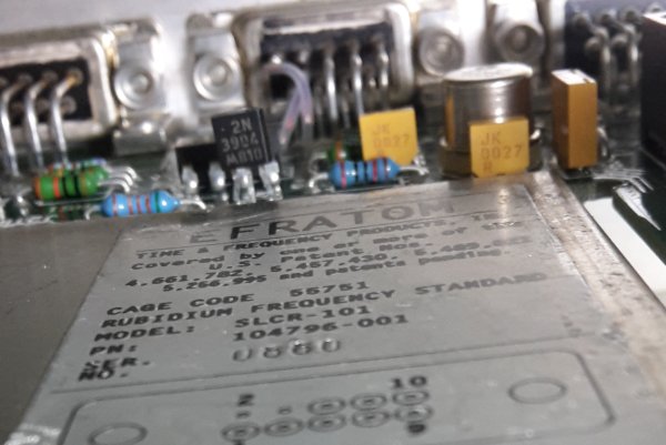
Fig 1.13.3
Since the "fault" LED on the front panel is off, and the green one alight, I assume it works OK.
The internal box does have an "ext C field" input, but it does not seem to be wired to any of the front panel connectors.
Up to table of contents
1.14 An borrowed EGG timer
Model H314. I got this after I have done most of the other measurements. It's former job was in a Scientific Atlanta ground station. It is bigger (taller) than even the HP10811.
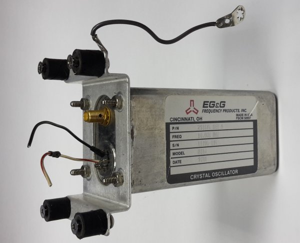
Fig 1.14.1
The label only says "crystal oscillator", but when switched on, it draws about 530mA, falling to somewhat less than 170 after 15 minutes, so it is definitely a OCXO.
On the bottom it has an SMA output connector, and seven terminals, arranged as an "miniature" 7 pin tube socket layout. Google knows nothing about it, and it seems that only two pins, gnd and +12V, are used. Other pins measure >20Mohm with an ohmmeter, and connecting them to ground or 5V with a resistor, does not influence the oscillator in any way. So, sadly, no EFC input.
It does have a mechanical tunung hole. But the mechanical tuning has a lot of backlash and hysteresis, and after each tweak, the frequency drifts for minutes or more, so extremely hard to tune better than to a few parts in 1E-8.
I was expecting better from such a big box. And it has no EFC input for disciplining, so it was of no further interest to me.
Up to table of contents
1.15 Three PTI XO5051-001 100MHz OCXOs
Bought on Ebay from .... Arrived with 10cm pieces of flat cable ending in a 4 pin female pin header, 10cm SMA to MCX cables, and some mounting hardware.
These are a bit alien at a 10MHz party, but I wanted to see what I get, when I divide frequency by 10.
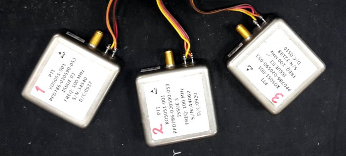
Fig 1.15.1
Could not find any datasheet online, just a forum post with the pinout.
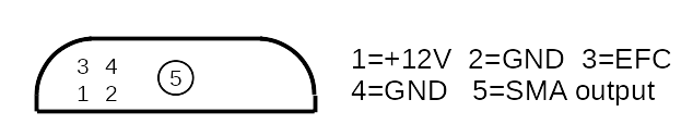
Fig 1.15.2
They need more than 6V to oscillate well, so I guess they are 12V types. When cold, they draw about 0.35A at 12V, and less than 150mA when warmed up. Tuning slope is 300Hz/V.
Two of them have a quite high output level: 5.8Vpp open, 4Vpp into 50 ohm, so the output impedance is less than 50ohm.
The third one had a much lower output level, about 1.2Vpp, but otherwise (stability, tuning, output impedance) seemed to work well. Neither the oscillator nor the output stage could be bad, so I decided to open the can and see.
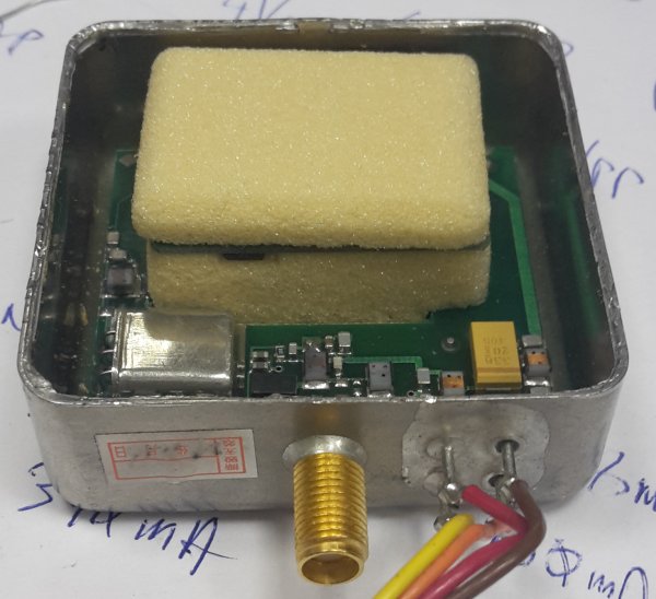
Fig 1.15.3
The oven part is thermally insulated by a hard, but brittle foam. The small daughterboard inside has additional cutouts around the oscillator part, to further reduce thermal conductivity.
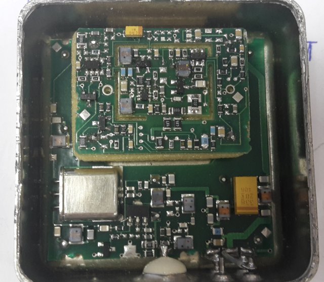
Fig 1.15.4
The part responsible for the low output level was a crystal filter between the oscillator and the output stage (the small UM-1 package). It's task is to reduce the far away (>20kHz) noise level. The crystal inside is probably very thin, and didn't survive the Chinese scrapyard processing pipeline.
I simply bridged it with an 220pf cap, and the ouput level was equal to the others. The far off noise reduction was of course gone, as can be seen in the phase noise measurements below.
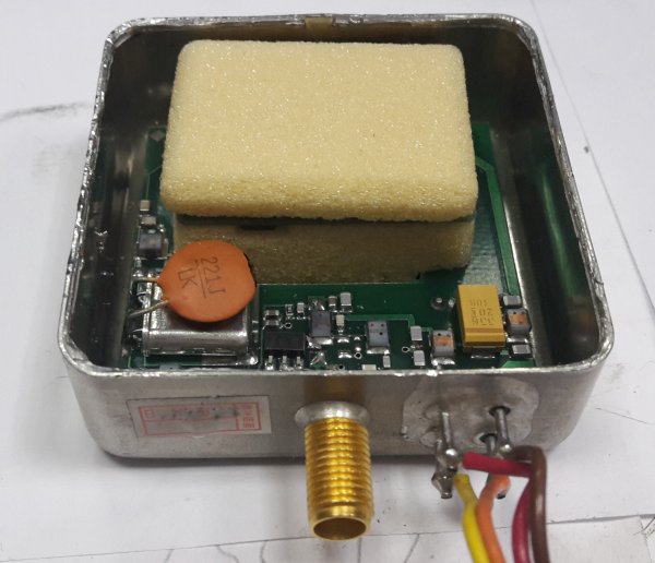
Fig 1.15.5
The output transistor (SOT-89 near filter) is marked N4 P48. Judging by the voltages on it's pins, it is a bipolar one.
I won't blame the seller. The output level was still high enough, to drive most if not all frequency counters. He probably connected the OCXO to a counter, and got a nice 100MHz reading, so he put it in the "good" bin.
To be able to compare to the 10MHz sources, I made a small dual channel frequency divider by 10, using the SN74AC163 counters from Texas Instruments:
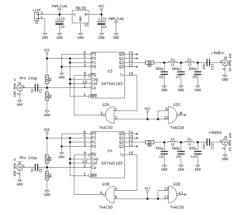
Fig 1.15.6
The PTI OCXOs have high enough output amplitude, to drive the counters directly, no additional circuits required. I built this with 0805 passives on a protoboard with groundplane (I bent every other SOIC pin upwards, to use the 2.54mm raster protoboard, the AC00 is DIP on the top side):
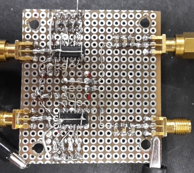
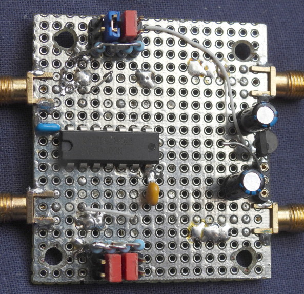
Fig 1.15.7
On terminal count, 0110 (6 decimal) is jammed into the counter, so that it counts from 6 to 15, for a division by ten. (The "P" inputs of the counters are connected to jumpers, so other division ratios can be set). Output is taken from Q2 instead of Q3, because the waveform there is more symmetrical (4:6 instead of 2:8). The 11MHz lowpass filters on the outputs make a nice sinewave, with a quite clean spectrum:
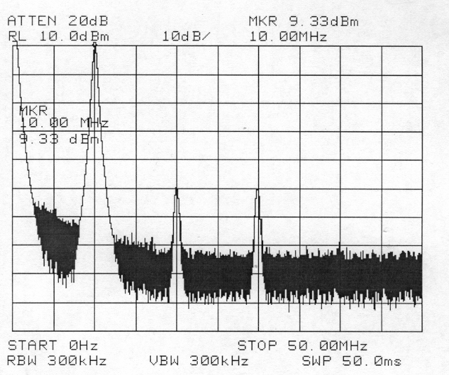
Fig 1.15.8
The dividers work up to about 130 MHz, so we have some margin. I was surprised that the output of the SN74AC163 chip is quite powerful. When loaded with 50 ohm, the output drops from 5 to 4 volts, so the output impedance is just 12.5 ohm! Using a series 33 ohm resistor, to make a quasi 50 ohm output, it can give almost +10 dBm! This is enough for around -175dBc/Hz noise floor on the HP3048.
These dividers also proved to have pretty low residual noise, see the phase noise measurements below
Up to table of contents
1.16 Four HP E1938 OCXOs
Bought on Ebay. E1938 were the last OCXOs developed by HP, before it became Agilent, and were, for example, used in HP Z3815A GPSDO boxes. They are much less well known / popular than the HP10811s, so despite being much rarer, they are usually sold for significantly less - so I could afford four, HI. I bought them from two sellers, two from each. E1938 number two is "Rev. B", others are "rev. C".
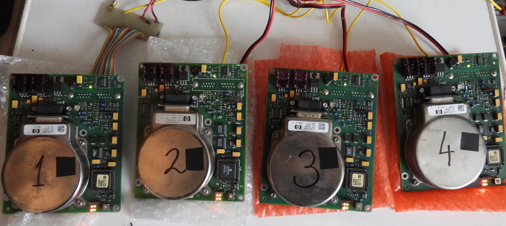
Fig 1.16.1 Four E1938 OCXOs warming up. The pieces of black insulation tape are thermal camera targets.
There seems to be no official user manual, probably because these were only sold as OEM parts, not as stand alone components. I could only find a couple of web pages: leapsecond (external link) and prc68 (external link), where some info, including pinouts, schematics and theory papers can be found.
These OCXOs were specifically designed for GPSDO applications, so the developers focused mainly on short term thermal stability, not so much long term stability and aging - these were expected to be taken care of by GPS. Another design goal was to make them low enough to fit in a 1U rack box.
This thermal design is called a "zero gradient crystal oven" (see the PDFs on the prc68 page). Ideally, it should be spherical, but there was the low profile requirement, hence the "hockey puck". It is a single oven, but still built like Solomon's temple: the porch (main board with digital stuff), the sanctuary (a circular PCB inside the puck) and the holy of holies, in the center of the puck (the crystal with a few components).
E1938s are much more complicated than the HP10811s, they contain at least ten times the number of components. The oscillator is a special bridge circuit with AFC and ALC circuits, oven controls are digital with A/D and D/A converters, there is a microcontroller overseeing it all, etc.
There is no provision for mechanical tuning, so if these age out of the EFC range, you're out of luck. With the EFC input grounded, mine were about 3 to 7Hz low, and need 3.2 to 4V of EFC to reach 10MHz. Now, I could find no info on the EFC voltage range in the available descriptions. The 10811s have no negative supply, but their EFC voltage range is -5V to +5V, so I wasn't sure.
Looking at the schematic, the EFC input, besides to the varicap diode at the crystal, also goes to an input on the 24bit A/D converter. There is only a three stage RC lowpass in between, no resistor to ground, so the full EFC voltage impinges on the A/D. According to prc68, this is an Analog Devices AD7714. It's datasheet specifies an absolute maximum analog input voltage range between -0.3V and AVdd+0.3V. The schematic shows it supplied with 5V, so a EFC voltage between 0 and +5V should be safe.
The tuning sensitivity is from 3 to 4 Hz/V, about ten times higher than on a 10811. This is not optimal for phase noise, but was probalbly done to cover the absence of mechanical tunung.
To get exactly 10MHz, the EFC voltage on boards 1...4 is: 4.0V, 3.25V, 3.2V and 3.4V.
Another mistery are the LEDs on the main board, there is a single one, and a group of four LEDs of different colors, that light and blink in various ways. The single one seems to just signal the presence of the +5V supply voltage. I could find no info about the other four. Looking at the schematic tells nothing, they are just connected to microcontroller's port pins. On power up, the four grouped leds will all blink in unison for a few seconds, then go into orange lit, green blinking, other two off, for the next ten minutes or so, the time probably depending on ambient temperature. After that, for about a minute, both green and orange will blink, with the orange led blinking "TN" in morse code. Finally, only the green led will keep blinking, others off. The green one blinking and others dark seems to say all is well, oven stabilized etc. I've also seen this blinking green meaning "OK" in some GPSDOs.
Power supplies needed are 5V and 12V. The oven and some digital circuits are driven from 5V. Cold, it sucks around 3 amps, going down to about 1.5A when it reaches working temperature, some 7 minutes later, in a 22C environment. I try to run my OCXOs from linear power supplies, so I really hate such large currents at low voltages.
Apart from the puck itself, there are two TO220 FETs on small heatsinks, that also get very hot.
The puck heats up to about 53C, and the TO220 heatsinks I measured between 70C and 100C.
Supply voltages for the oscillator and other analog circuits, are derived from the 12V supply, using LT1121 LDOs. Consumption here is much lower, about 95mA.
After warming up, it will continue to work with the 5V supply down to 4V, probably depending on the ambient temperature. As for the 12V supply, the orange led starts to blink at 10.5V.
The power on transient on the 5V supply was quite similar on numbers 2, 3 and 4:
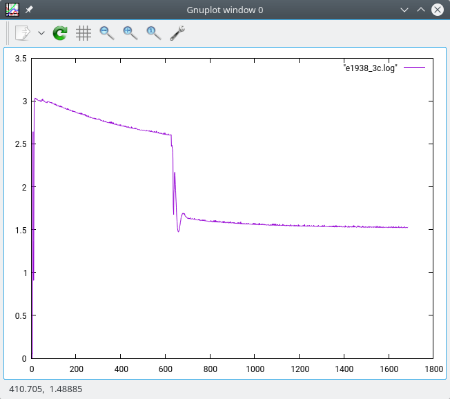
Fig 1.16.1 Current versus time graph, vertical: amps, horizontal: seconds
but number 1 throws some tantrums before stabiizing:
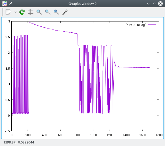
Fig 1.16.2 Current versus time graph, vertical: amps, horizontal: seconds
The main connector is a D25 female like thing with a coax terminal in the middle. The coax in the center is not used, both 10MHz output and EFC input are on the remaining 20 pins. I just used a normal D25 male connectors, put them under a drill press, and massacred a hole in the middle, to get rid of the center five pins.
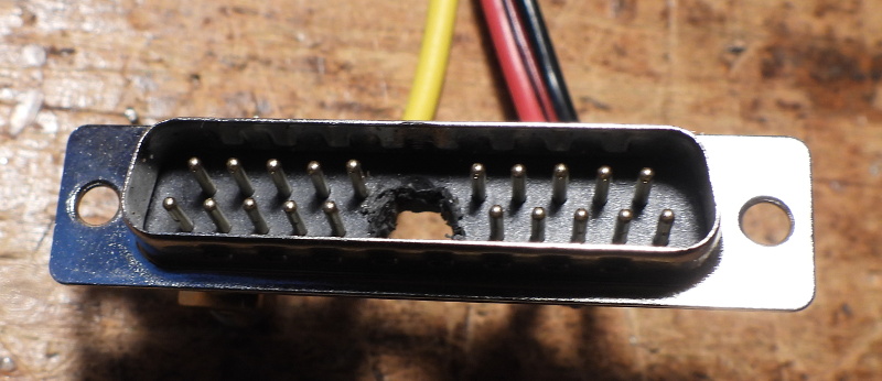
Fig 1.16.3 A massacred D25 connector
Then I connected wires for GND (black), +5 (red) and +12V (yellow), a female SMA (card edge type) for the 10MHz output, and a two pin female header for the EFC voltage.
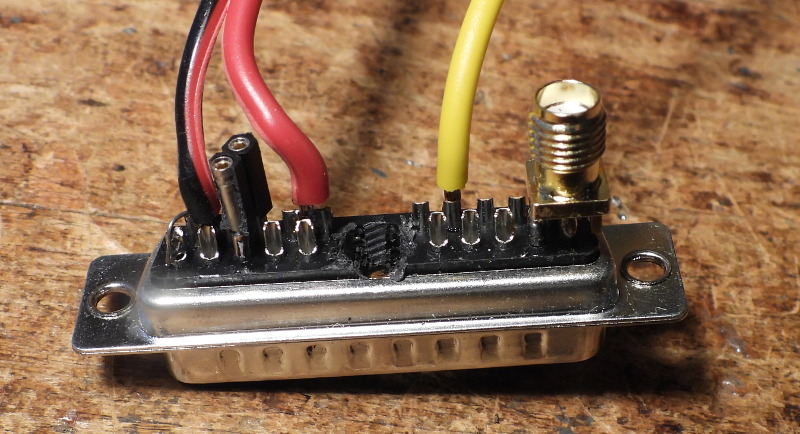
Fig 1.16.4 Connections to the back of the massacred D25 connector
There is no potentiometer for setting EFC on the OCXO, so for testing, I made a small proto board with a 78L05 and a trimmer pot.
NOTE: there is a trimmer pot on the main board, near the puck connector, but it does not control the frequency. It is connected across the 10MHz output.
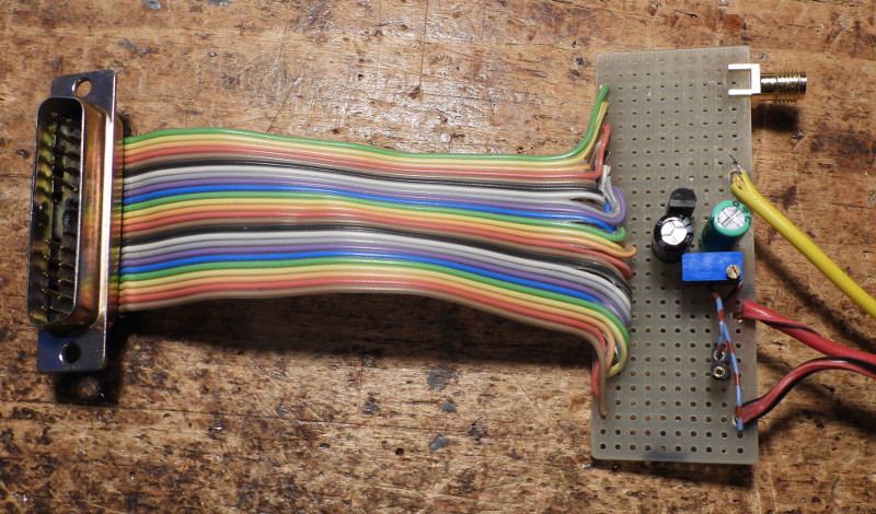
Fig 1.16.5 Proto board for EFC setting
The EFC tuning sensitivity is around 3.8 Hz/V.
Pulling by the 12V supply is about 3 mHz/V, tested from 11.5 to 12.5V. I also varied the 5V supply between 4.5 and 5.5V, but the change of frequency was smaller than the random variation.
The E1938 OCXOs were quite a disappointment for me. On the leapsecond.com page, there are some measurements, and one example has ADEV below 1E-12 up to 1000 seconds, so I was hopful. Considering all the fancy theory, complicated schematic, power consumption, and younger age, I expected them to be at least slightly better than the 10811 - but they are quite a bit worse (see the measurements below). Since I have four of them, from two different vendors, and none is even close to a 10811, the probability that I just had bad luck, is not very high. Maybe I am starting to understand, why you can buy four of these for the price of a single 10811D?
But I still have a hard time believing that HP would do such a step backwards? Could it be that these just don't age well? There are eleven orange tantalum caps on the main board, but my "MESR-100" measured all of them below one ohm, I guess that's OK?
Since they looked like they haven't seen any electricity for years, I tried to give them another chance, by connecting all four to an old PC PSU, and let them run for a long time. After five months (!), I could not see much improvement. So, maybe this fancy design was just to get low profile, at whatever cost in performance that would bring?
On one of the above linked sites, there is also a zip file with a program for communicating with the E1984 over the serial port. I wondered, it might provide some status report, useful for debugging. I tried to run it under WINE, and it didn't work. Then I borrowed a laptop with windows 10, still no luck. A dumpster laptop with windows XP
Up to table of contents
1.17 Two LPRO rubidium boxes
Bought from Ebay, advertised as "high lamp voltage". These are "fully analog", no microcontroller. Only two status lines are provided, lamp voltage and ....
Power supply is 24V, switch on transient looks like this:
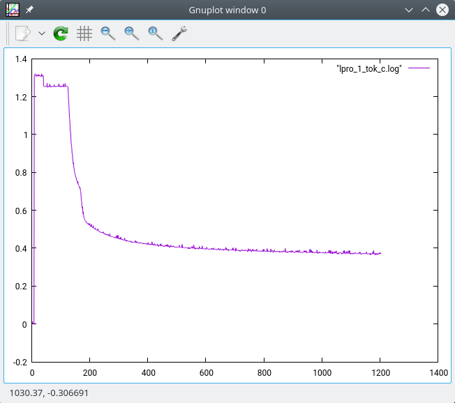
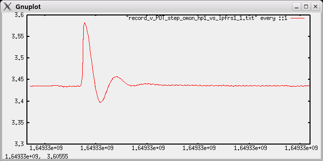
Fig 1.17.1 Current versus time graph, vertical: amps, horizontal: seconds
The lamp voltage, after power on, goes like this:
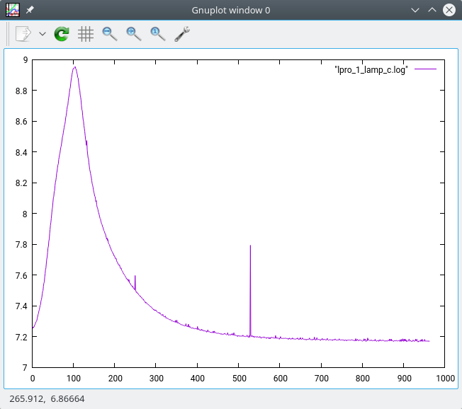
Fig 1.17.1 Voltage versus time graph, vertical: volts, horizontal: seconds
Up to table of contents
1.18 A HP Z3805A GPSDO
Lately, I came across a 12 year old (from 2012) post on the time nuts forum, where user Said Jackson talks highly about this box. The vendor he bought from, still sells these on Ali, with 100% positive feedback, so I decided to buy one.
It arrived super well packaged, and looked like new. The only hint of previous use was some marring on the D25 and XLR connectors. It is a very nice "old style HP" box - much bigger than most modern GPSDOs. It is ancient technology, but being based on a high performance DOCXO, it shouldn't be worse than cheap modern ones.
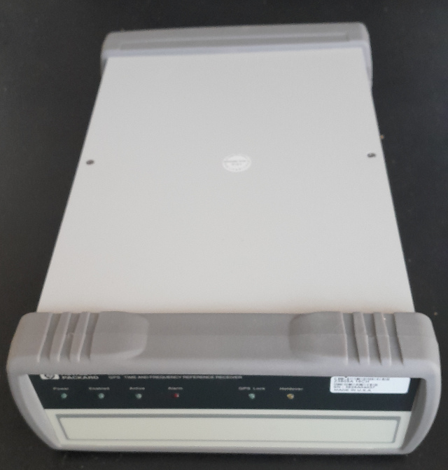
Fig 1.18.1 The Z3805 box
I still haven't installed a GPS antenna at the new place, so I decided to power it up without antenna, just to see if it outputs ten MHz, and communicates on the serial port.
There are two supply options, 28V and 56V, but none of the checkboxes on the back side were checked, so I started with 15V and slowly increased the voltage.
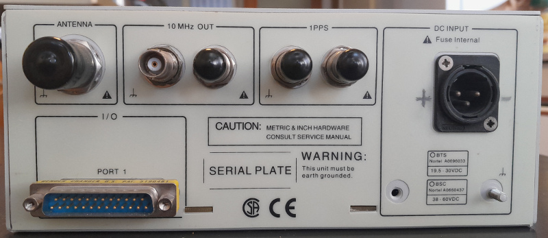
Fig 1.18.2 Back side. The plus and minus marks are by me, had to open the box to see, have no manual.
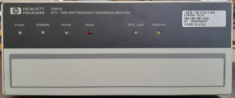
Fig 1.18.3 Front side
It drew almost no current (<25mA) up to 23.5V, when the LEDs came on, and the current rose to about two amps. It kept at 2A for a few minutes, then slowly decreased to about 0.85A, in less than an hour.
So it seems it is the 19.5...30V type. It will not start at 19.5V, but once started and warmed up, it works down to 19.5V
The guts look like this:
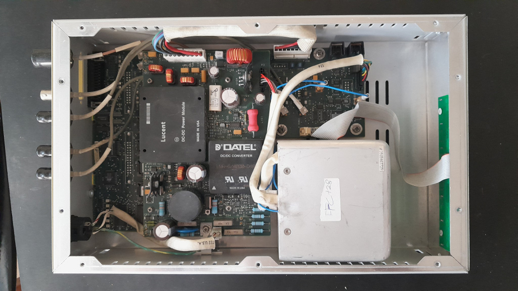
Fig 1.18.4 Z3805 guts, with top board. The DOCXO is probably a 10811, inside an outer thermostat box. The box is full height of the instrument.
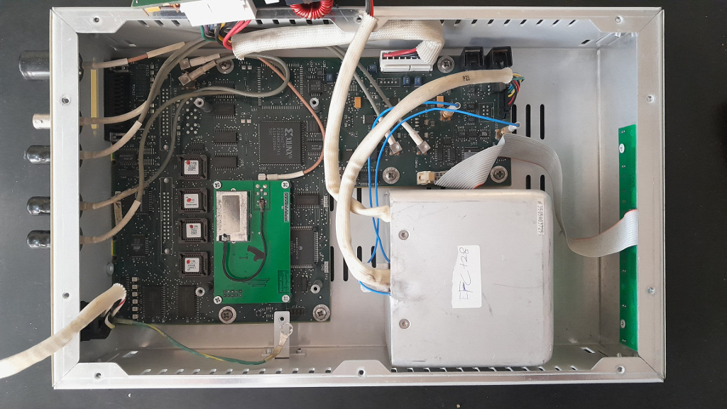
Fig 1.18.5 Z3805 guts, without top board. The little tin box on the green board seems to be the GPS receiver.
The top board seems to be the power converters and distribution, the smart stuff is on the bottom board, based on a MC68331 microcontroller and a Xilinx XC3042 FPGA.
Since this is a device best kept powered up constantly, a dedicated power supply makes sense. I have a box of old laptop PSUs, which are mostly 19 or 20V, so shouldn't be too hard to convert to 24V.
I opened one, and it had a very simple regulation circuit, based on a TL431 and optocoupler feedback.
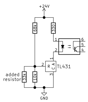
Fig 1.18.6 Schematic of the PSU regulation circuit (TL 431 pins 2 and 3 are swapped)
I simply added parallel resistors to R1, until I got a bit more than 24V, with a 33k resistor. (the 39k on the photo below gave 23.5V)
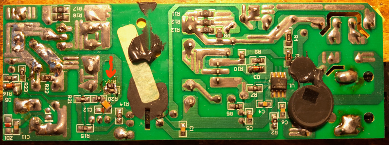
Fig 1.18.7 Photo of the parallel resistor (red arrow)
The output electrolytic capacitors were 25V types, so I replaced them with 35V types of a lower value, but same size. The supply was rated for 4.7A output, so at the less than 1A consumption of the 3805, the ripple should be OK with the smaller caps. Last, I replaced the HP barrel plug at the end of the cable with a XLR, to fit the 3805.
These boxes are glued/welded together, so I did not bother trying making it nice, just used a couple of zipties to shut the box.
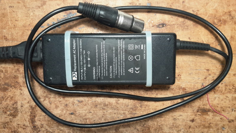
Fig 1.18.8 Photo of the finished PSU
Usually. it makes sense to supply precision oscillators from a linear supply, to avoid interference. But the Z3805 box itself contains three switching converters, so I think a linear supply wouldn't bring much improvement.
I could get responses over the RS232 port on the first try (9600, 8N1). The status page reports all self tests passed, and the last location half way between Kobe and Osaka in Japan.
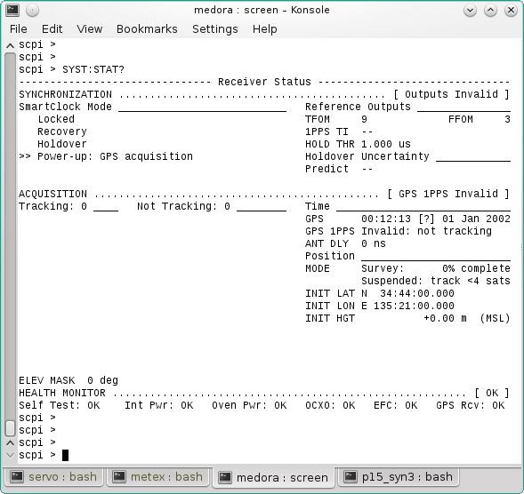
Fig 1.18.9 A screenshot of the Z3805 status page
The normal prompt (after power up) is "scpi >", but after a bad command, it changes to "E101->" or similar, and stays so, even after subsequent correct commands.
Up to table of contents
1.19 My HP8663 signal generator
When it was introduced in the 80's, this was the lowest noise signal generator, and it held the title for more than a decade. Even today, there are not many better ones out there.
These were very expensive when new, but now go for very reasonable prices on the used marked. I guess their size, weight and power consumtion make them less popular. I bought mine a few years ago, at the Friedrichshafen HAM radio flea market.
The HP8663 is based on a special switched inductance low noise VCO, with a HP10811 10MHz OCXO as the master reference. The 10MHz reference is available on the back panel, but 10811s are described elsewhere on this page, so here I write about the front panel main output, when the frequency is set to 10.0 MHz. For the same reason, I did not make separate frequency stability tests, the ones for the 10811 should be representative.
Up to table of contents
2 What and how it was measured
First, some general characteristics, like power consumption, tuning sensitivity, supply pull, etc. were measured.
Next, phase noise with my HP3048 system, and longer term phase/frequency stability with my FRCOMP setup.
These are similar measurements, the main difference is that HP3048 measures short term deviations, in the range up to 100 seconds (frequency offsets from 0.01Hz upwards) and Frcomp measures long term deviations, from approximatley one second up (frequency offsets 1Hz and below).
I do not have the facility to simultaneously measure many oscillators, so I mesured them sequentially. I could only dedicate a week or so to each oscillator, so, surprise, one year aging I did not measure. Each oscillator got up to a week warm up time, then I did the measurements.
In most cases, precision oscillators are charcterized by their Allan deviation (ADEV) curve [1]. That is a statistical measure, which in one graph tells the overall performance of the oscillator, at various timescales.
But because ADEV is based on averaging, a short spike will just slightly raise the curve over a broad band of offsets, indistinguishable from a low level broadband noise - you will never know that the oscillator itself is better, and the curve could be lower, if you just wouldn't happen to bump into that cable.
If you are buying na oscillator, ADEV should be your guide. But I was interested in a more detailed observation of the behavior of various oscillator types, how they react in real time to different changes in the environment, etc.
For that purpose, a high resolution frequency-vs-time graph is hard to beat. Changes caused by temperature, supply voltage, output load, etc., can be observed in real time. Regulation loop time constants and dampings can be deduced, and so on.
Up to table of contents
2.1 Phase Noise
I am mostly interested in VHF and above stuff, so I was very interested in the phase noise.
For phase noise, absolute values can be obtained by the "triangular hat" method, measuring all three possible pairings of three sources, and then solving a system of equations. The HP3048 software should be able to do the math for you, but mine (an 'opt301' DOS version) somehow does not want to do it. No error reported, simply nothing happens, when I select the option. Luckily, the math is not very complicated, can also be done manually.
Once you have one well characterized oscillator, you can measure others with equal or higher noise against it. If their noise is similar, you must deduct the reference oscillator noise. Again, the software should do that, but mine won't. If the measured oscillator is much noisier, you can just take the result as-is.
To avoid measuring too many triplets, my strategy was to find the best source(s), and then measure the others against them. There is not necessarily a single best source, one might have lower close-in noise, and some other the lowest far out noise floor.
When two oscillators of the same type are available, assuming their noise is equal, they can be measured against each other, then 3dB subtracted from the result. To check that they are about equal, they can be measured against a third one, whose noise should not be much higher. In any case, you can be sure that neither of the two is worse than the measured result.
In the end, I found the HP10811 #3 to have the lowest noise over most of the range. The Epsons were comparable around 1 Hz, but most other oscillators had higher noise, so I used the HP10811 #3 as the reference in most measurements.
When measuring phase noise, the power supplies used can influence the measurement, especially line harmonic spurs, the 'line porcupine'.
When measuring two identical oscillators, using the same supply for both can help. Using batteries is even better, since you can get rid of multiple grounds.
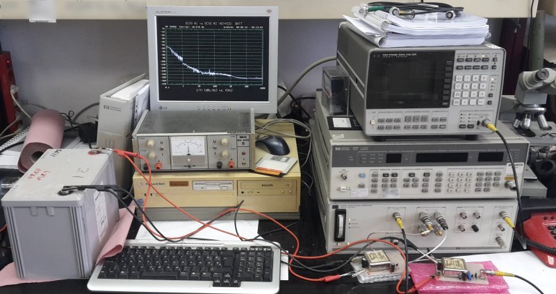
Fig 2.1.1 DUT oscillators supplied from a battery
I have put the OCXOs on folded bubble wrap, to isolate them somewhat from mechanical vibration of the table (fans, people (me) walking around...).
Here is a GIF animation of measuring the same oscillators with separate supplies, with a common supply, and with a battery. You can watch the line porcupine turn into a small hedgehog, and then vanish completely!
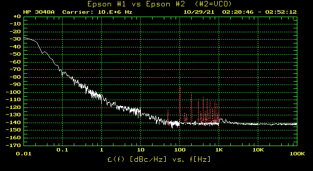
Fig 2.1.2 Measurement with separate supplies, common supply and battery
Could be, that this was for the first time in my life, to see a spurless phase noise graph, live or in literature...
Note that in the common PSU measurement, some noise has intruded in the 3...10Hz range. Such are the vagaries of phase noise measurement. Often you need to repeat the measurements, or increase the averaging.
The default averaging factor is 4. For most measurements, I set it to 64 (marked "avg64" in the title). When set to 64, the curves are much smoother, but one measurement down to 0.01Hz takes many hours.
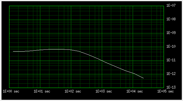
The noise floor of the HP3048 depends on the input levels. With the levels produced by the oscillators presented here, it was below -170 dBc/Hz.
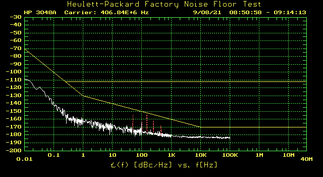
Fig 2.1.3 The system noise floor, as measured with HP11848 internal oscillator.
For most of the following phase noise measurements, HP10811 #3 was used as the reference, whose phase noise I determined using the "triangular hat" method, with the other two HP10811 oscillators I have.
Subtraction of reference oscillator noise does not work in my HP3048 software, so in the following measurements, the noise of the HP10811 is not subtracted. But most of the DUTs here have high enough phase noise, that the HP10811 does not conribute significantly.
I am running the HP3048 software on an old DOS box with bad battery (the stupid Dallas black box), so the dates and times on the graphs are mostly random numbers.
Up to table of contents
2.2 Frequency Stability
As far as long term stability goes, I have no optical mesh atomic fountain hydrogen maser turbo cesium reference, so the sources were just pitted against each other. For very long times (more than one day), I used one of the GPSDOs, and for medium times (seconds to hours) one of the rubudiums. The rubidiums were checked against GPSDOs for longer term stability.
This was OK for me, since for the interferometer, I just need independent sources that keep synchronization as well as possible.
Some of the measurements on this page I have already presented on the FRCOMP page, but there the emphasis was on testing the Frcomp performance, while here I focus on the sources themselves.
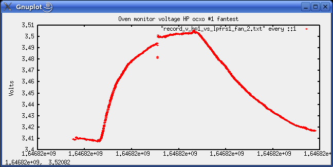
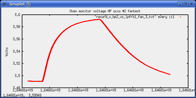
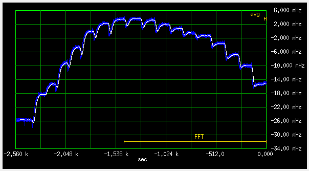
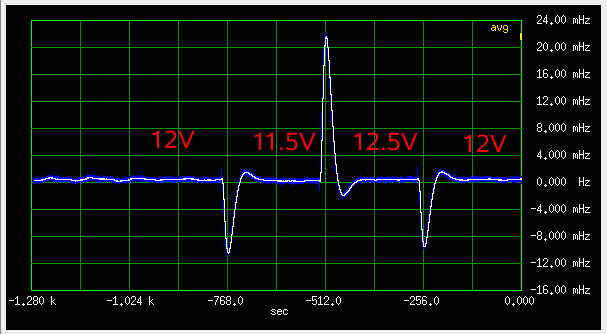
During the stabilty tests, I also checked the supply voltage pull, and did a "fan test", to see how the thermostats perform. I put a small fan about 10 cm from the OCXOs, and switched it on and off.
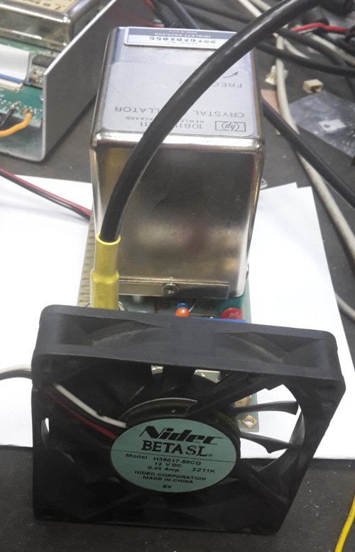
Fig 2.2.1
NOTE: Symbolic image - the fan is reversed, to show the label, and is not running.
This is quite a brutal test, in real life you wouldn't expose your frequency standard to such harsh thermal shocks. I've run the 12V fan at 8V. At first, because of my mistake, and later, because I didn't want to redo the measurements already done.
Any real temperature characterization would have to be done in a thermal chamber, but the fan test proved to be very useful for thermostat problem detection, and fine adjustment of thermostats.
3 Measurements of phase noise
3.1 HP10811
After some playing around, these seemed to be the best of my oscillator collection, so I decided to do the "triangular hat" measurement on these, to determine their phase noise characteristics. The measurements of the three possible pairs is shown below as a GIF animation:
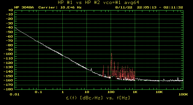
Fig 3.1.1
From these, I calculated this:
    0.01Hz  0.1Hz   1Hz     10Hz    100Hz  1kHz    10kHz  100kHz
#1  -40.3   -74.6  -106.2  -135.7  -156.3 -162.3  -162.0  -162.4
#2  -41.0   -73.5  -105.2  -136.0  -157.1 -162.3  -164.3  -163.8
#3  -44.8   -82.2  -119.0  -149.7  -159.2 -163.8  -165.8  -166.7
So, #3, the "D" type, came out the best. The difference is quite big, which is not that good for the "triangular hat" accuracy, but that is what I have. Should buy a couple more "D" types, but their prices went through the roof lately.
The phase noise specification for "D" type is
    1Hz     10Hz    100Hz   1kHz    10kHz
#1  <-100   <-130   <-150   <-157   <-160
which is surpassed by a big margin.
The HP10811-60111 type has no phase noise specified, but both of mine are within the "D" spec. HP really ruled the (micro)waves, while it lasted.
Up to table of contents
3.2 Epson Toyocom TCO-6920
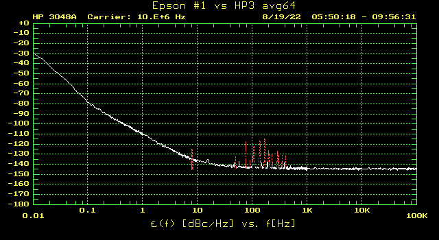
Fig 3.2.1
Between 0.1 and 10Hz these are very good, competitive with the HP10811s. But 100Hz and above, they are much worse.
There is some difference between the two, but I guess, with surplus stuff from Ebay, one can expect that.
Up to table of contents
3.3 Trimble 65256 OCXOs
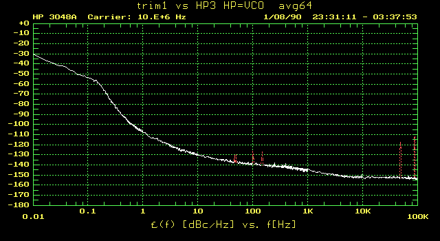
Fig 3.3.1
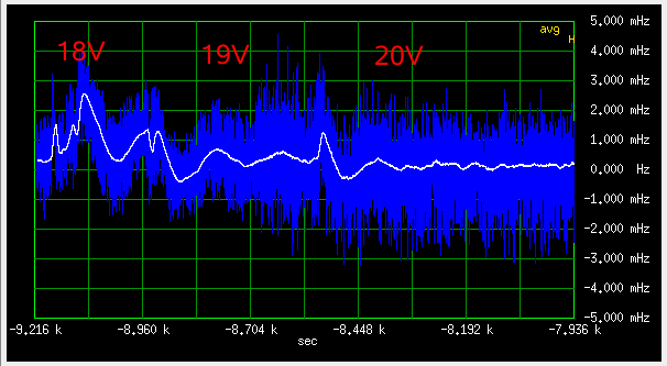
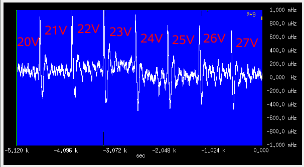
These two are a 12V type (trim1, date 0640) and a 5V type (trim2, date 0918), so the difference between them is not surprising. The hump at 0.1Hz in the 12V type is real, I have repeated the measurement several times, and it was always there.
For the 5V types, I added a 7805 to the test board, maybe that's why there are no spurs. But Bliley and CTI below, were measured on the exactly same test board and setup, and the line spurs are there.
Up to table of contents
3.4 Bliley NV47M1008
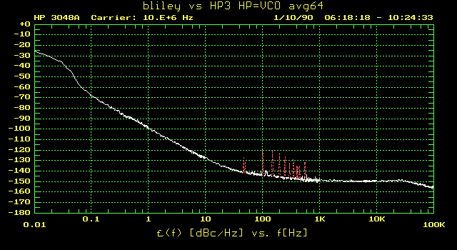
Fig 3.4.1
Up to table of contents
3.5 EGG H314 OCXO
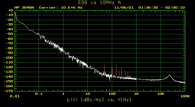
Fig 3.5.1
Up to table of contents
3.6 CTI OSC5A2B02
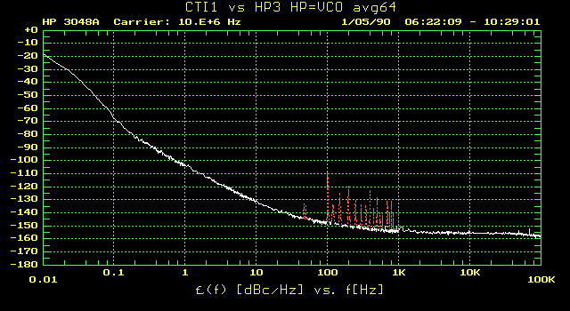
Fig 3.6.1
Regarding phase noise, these were a pleasant surprise, considering their price. I have a dozen of them, and they all measure consistently within a couple of dB.
Up to table of contents
3.7 The RFG-RB rubidium
I measured this one before I had the HP10811s, so it is measured against the HP11848 internal 10MHz oscillator A, which is similar to the HP10811. It was also measured without additional averaging, so the curve is a bit noisy.
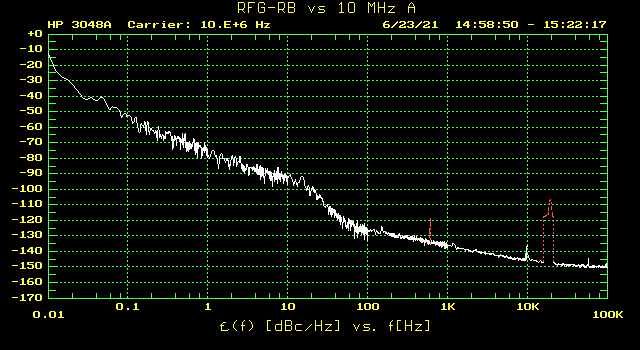
Fig 3.7.1
The phase noise between 0.1 and 100 Hz is significantly worse than the free running OCXOs. The rubidium "dip" is symmetrical, so the loop must be dithered, to keep the signal centered in the dip. Usually, in these oscillators, the dither frequency is a few hundred Hz. We can expect the loop to be at least ten times slower. There is a marked "PLL shoulder" above 10Hz, which indicates the bandwidth of the controlling loop. The fat dildo at 20kHz is probably from some dirty switchmode supply in the vicinity.
Up to table of contents
3.8 The LPFRS rubidiums
My three LPFRS rubidiums behave like this:
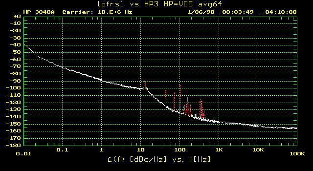
Fig 3.8.1
Lpfrs1 is the one I bought in working order, lpfrs2 and lpfrs3 are the ones I resurrected. Overall, the phase noise is 5..10dB lower than the RFG-RB.
In the 0.1Hz to 10kHz range, they have higher noise than a HP10811, up to 30dB worse at 100Hz. It would make sense, to have a "cleanup" HP10811 locked to the rubidium, with a slow PLL.
I do plan to design such a "cleanup" loop.
Up to table of contents
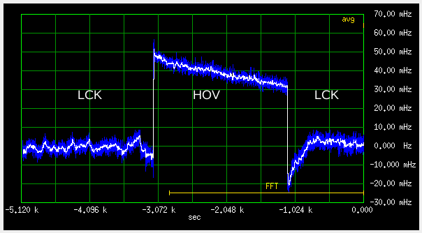
3.9 Trimble 57963-C GPSDO
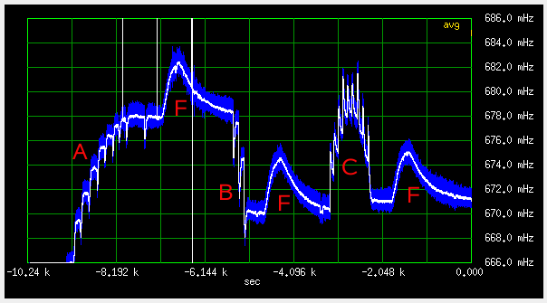
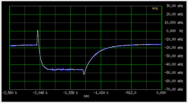
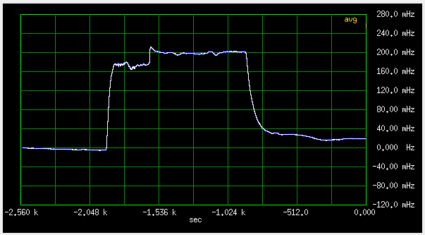
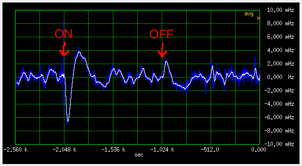
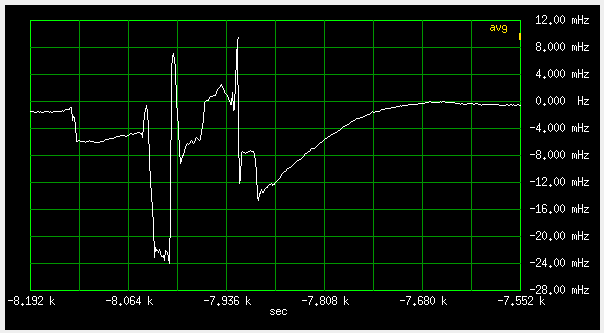
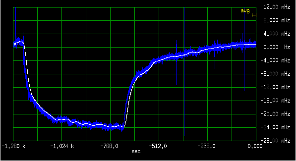
These have a funny disciplining loop, which abruptly shifts the frequency every second, see below.
In the phase noise spectrum, this shows as a sin(x)/x pattern up to ten Hz. The animation below shows a comparison between locked and holdover (antenna disconnected) states:
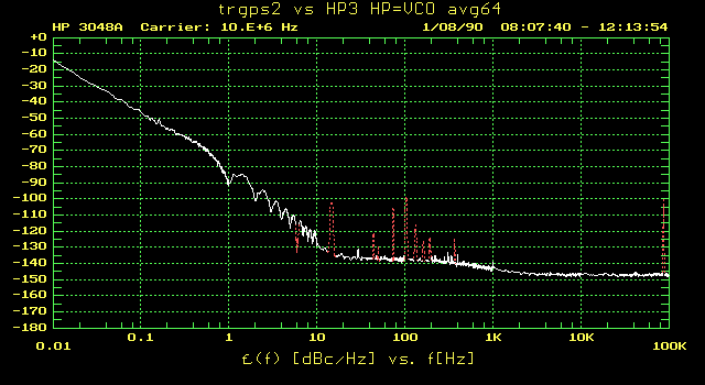
Fig 3.9.1
During holdover, the OCXO should perform like free running, compare trim2 (5V type) in fig 53 above. It even has a little lower phase noise, maybe because it is 6 years younger (1543 vs 0918).
Below 10Hz, disciplinig increases the phase noise, up to 25dB at 1.1Hz.
Up to table of contents
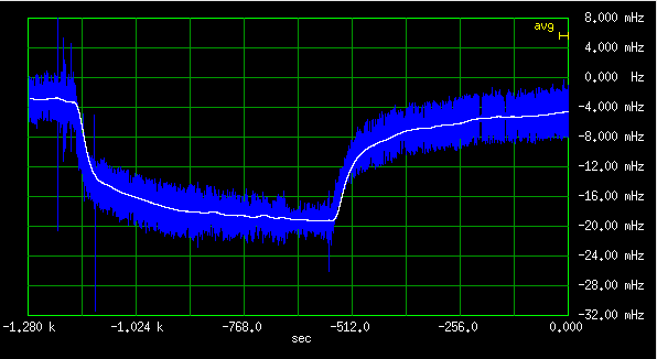
3.10 Oscilloquartz OSA 4350 GPSDO
To my surprise, this was a quite hairy animal:
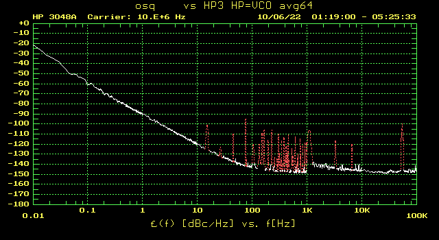
Fig 3.10.1
I tried all kinds of every power supply, including batteries, but the porcupine was always there. I could lay my hands on only one specimen of this species, so can't say for sure, that this is the typical behavior. Could just be an expired cap in the old box. It wasn't mine, so no surgery.
However, the supply voltage is specified as 18...60V. Say the OCXO inside runs at 12V, and the supply is 60V. A linear regulator would then cook off four times the power consumed by the OCXO heater. Therefore I am quite sure, there is a switching regulator inside the box, spiking up the spectrum.
This GPSDO also does some jumps in frequency, similar in size to the trimble above, but on average at much longer, quasi random intervals. It seems, it runs from uncorrected 1PPS pulses, see below.
This makes the effect of disciplining on phase noise smaller than with the Trimble, mostly seen here below 0.1Hz offset.
Up to table of contents
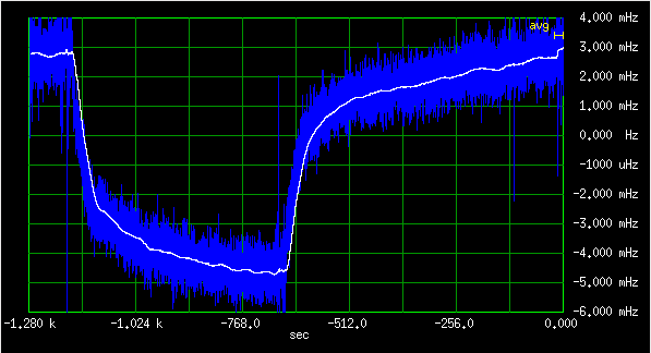
3.11 Quartzlock E8X GPSDO
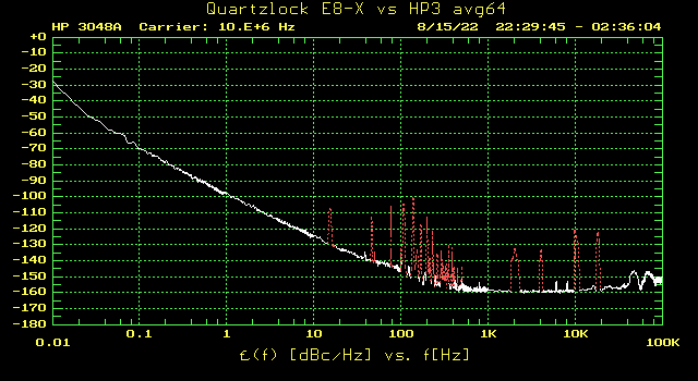
Fig 3.11.1
Good performance. I forgot to measure the holdover before returning it to the owner, so above is only the disciplined curve.
The two humps at about 50 and 70 kHz are real, they were there in every measurement. The noise seems to slightly increase towards 100 kHz, but my HP3048 software doesn't support the RF analyzers I have, so no measurement above 100 kHz.
Up to table of contents
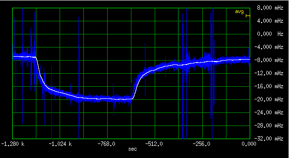
3.12 Cellsync 1100 GPSDO
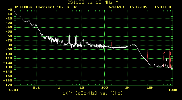
Fig 3.12.1
Quite horrible. Old box, maybe faulty caps or something? But despite that, is it still very useful as a frequency reference for counters, etc. Long term, as good as any GPSDO, just not suitable for frequency multiplication and synthesis.
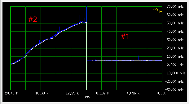
During holdover, it went outside of the electrical tuning range of my HP10811D reference, see below.
I did not want to mechanically retune the HP again, so I didn't bother to measure the holdover phase noise.
Up to table of contents
3.13 PTI 100MHz
I have combined all three measurements at 100 MHz into this animation:
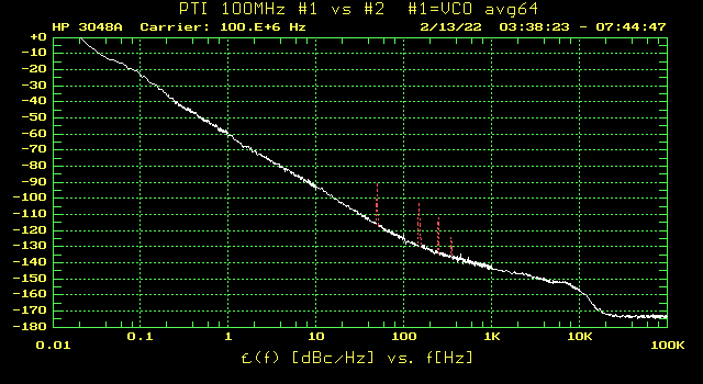
Fig 3.13.1
Number three (the one with shunted output filter) of course stands out at offsets above 10kHz.
Why the spurs are strolling up and down? Absolutely no idea.
Next, I used the /10 divider described above, to produce 10MHz signals. The following animation compares the results at 100 and 10 MHz, for oscillators #1 and #2 (the ones with filters):
Fig 3.13.2
A noiseless /10 divider should reduce the phase noise by 20dB. At offsets less than 30Hz that is almost exactly what we get. At higher offsets, then noise of the SN74AC163 starts to show, and above 300 Hz it dominates.
But -160dBc far away noise floor is still good, comparable to the HP10811, so the SN74AC163 can be used as a quite respectable low noise frequency divider.
Up to table of contents
4 Measurements of Frequency Stability
4.1 The rubidiums
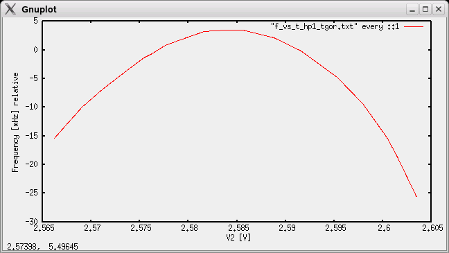
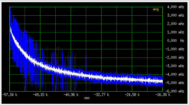
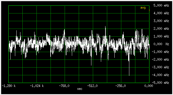
4.1.1 Long term
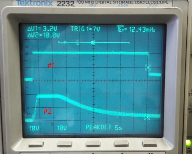
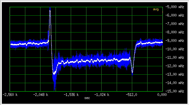
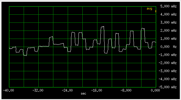
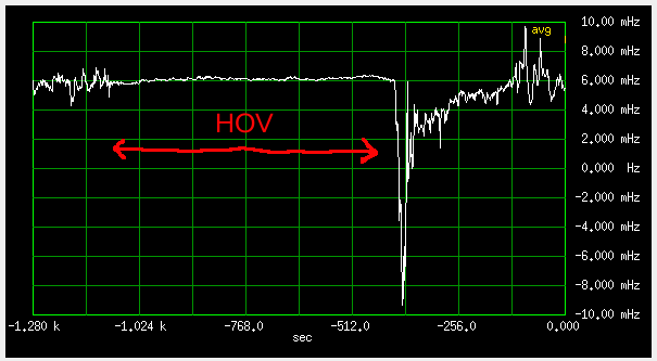
For longer term stability, I compared the lpfrs rubidium #1 with the Trimble 57963-B GPSDO #1. These Trimble GPSDOs are quite "jumpy" on a faster time scale (see
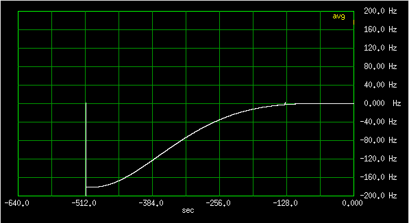
here), but over a longer time, this can be mitigated by averaging.
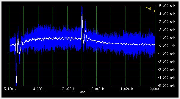
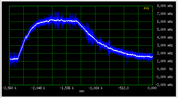
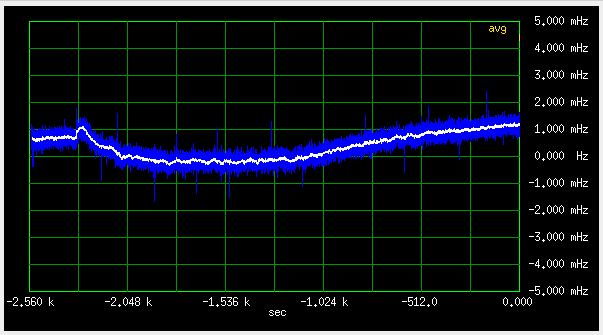
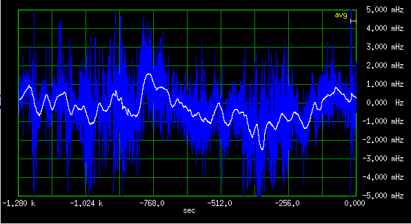
I let the measurement run for eight days (first to eighth of March 2022), so that a 24h cycle would nicely fall into a FFT bin. On a 1mHz/div scale, it's more or less a straight line:
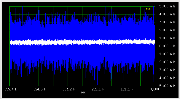
Fig 4.1.1.1
Blue samples are averaged for 1.365seconds, the white ones about 350 seconds.
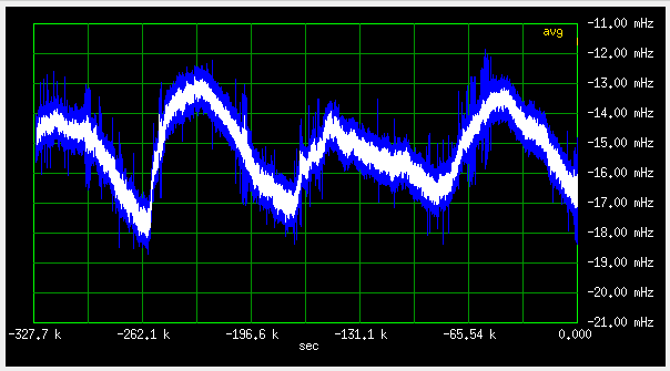
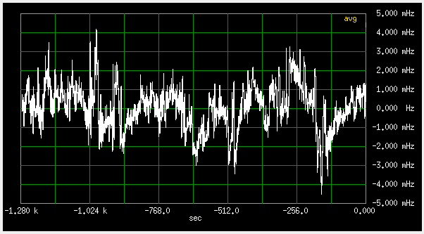
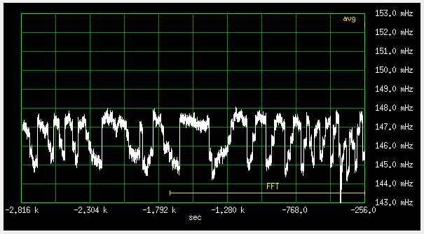
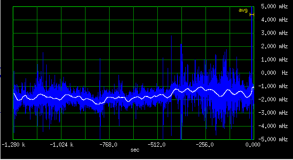
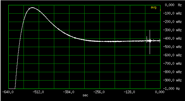
Expanding the vertical scale to 100uHz/div, shows a slow drift:
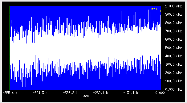
Fig 4.1.1.2
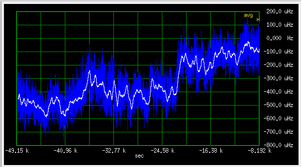
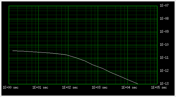
It is a nice linear drift, shouldn't be too hard to compensate. Linear regression shows 13.7uHz (1.3E-12) per day of drift.
Apart from the drift and the short term noise from the GPSDO, nothing much can be seen. The room temperature variations, and the ionosphere vary with a 24h cycle, but don't seem significant.
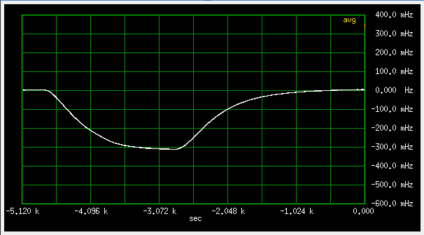
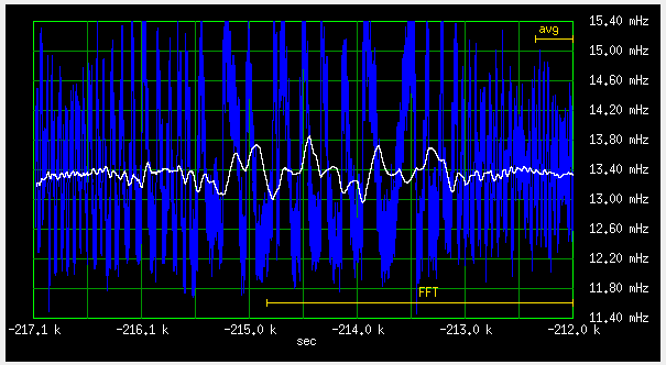
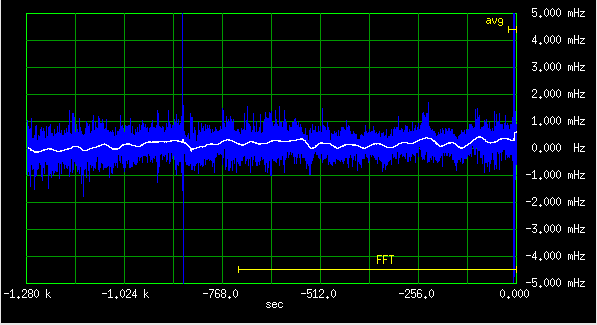
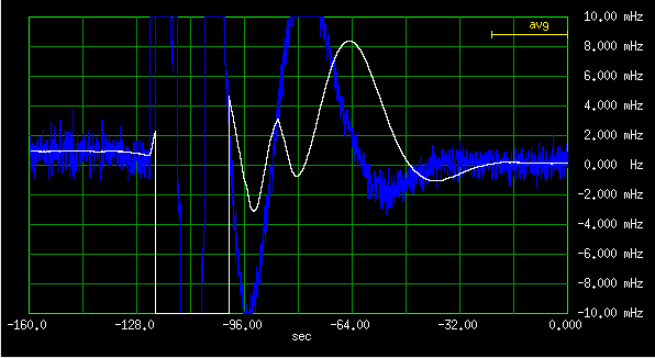
After removing the offset and linear drift, the one hour averages look like this:
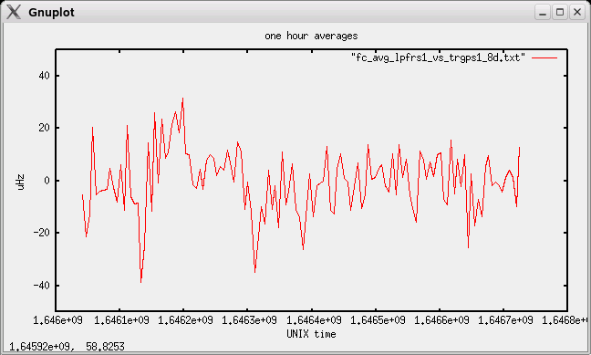
Fig 4.1.1.3
The temperature in the room varied a few degrees up and down:
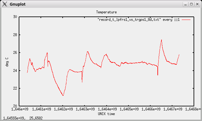
Fig 4.1.1.4
Maybe the dip in the temperature at 1.6462E9 could be correlated with the frequeny peak at the same time?
The Sun was rather quiet: (graphs from htpps://www.swpc.noaa.gov/)
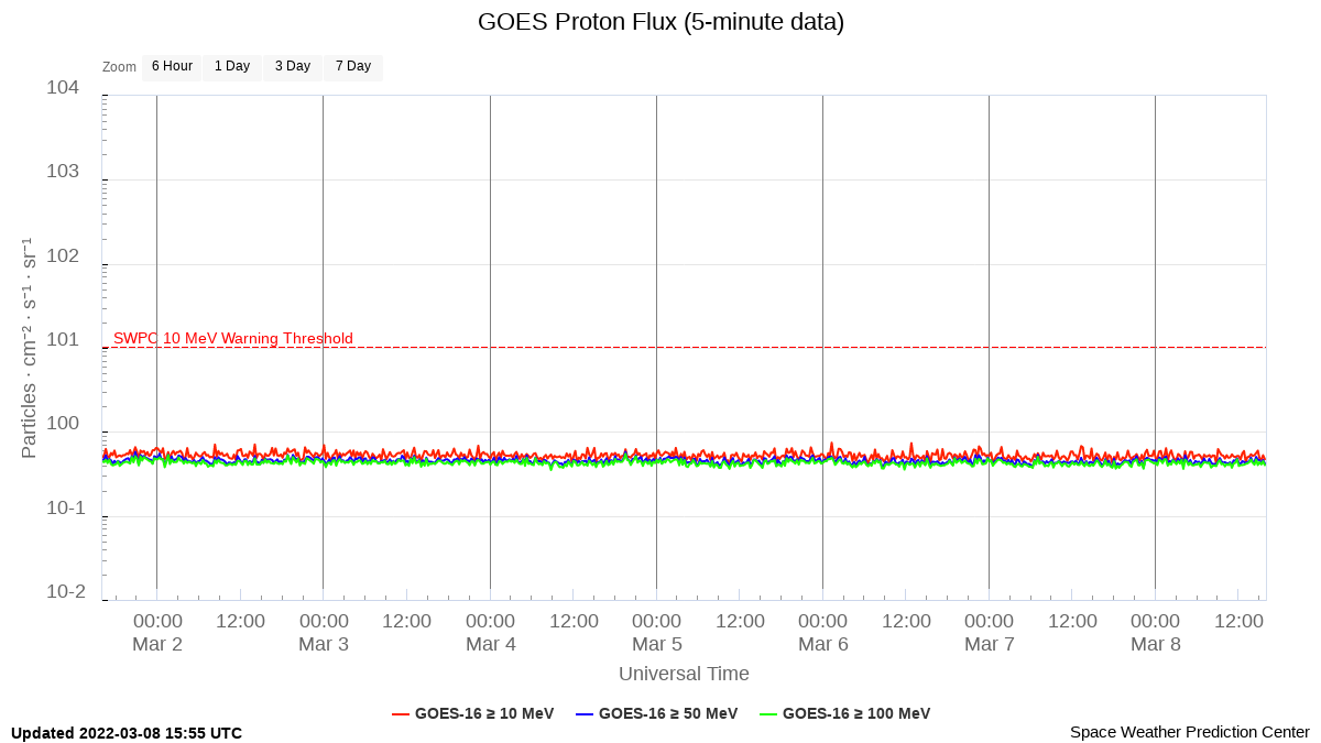
Fig 4.1.1.5
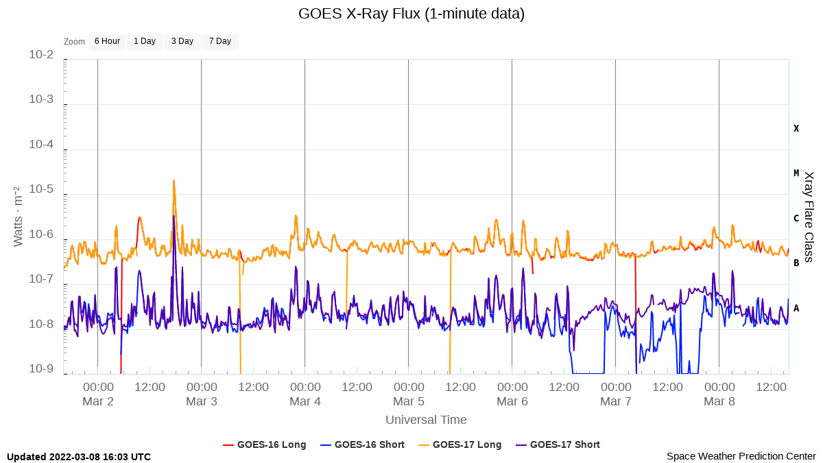
Fig 4.1.1.6
and beginning March in Slovenia, it stayed under 40 degrees of elevation.
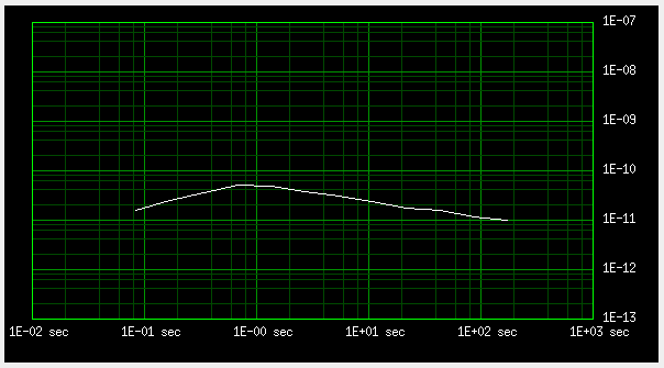
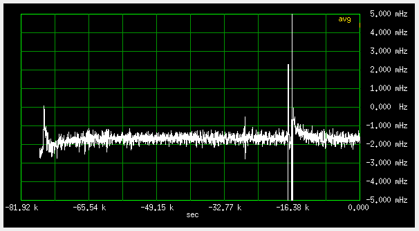
To see any periodic components in the frequency difference data, I did a 128 point FFT:
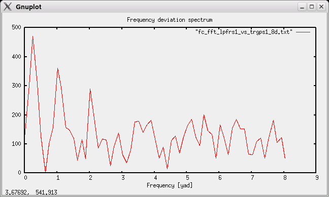
Fig 4.1.1.7
1yad = 1cycle/24h, approx 11.574uHz. There are peaks at 24 and 12h, but not very high, maybe 6dB above noise peaks. There is also a higher peak in bin 2 (96h cycle) - no idea where that came from. It is not the crosstalk beat - at 500uHz difference, that would have a 33 minute period, not four days. Probably just a fluke - don't want to repeat the 8 day measurement which ties up some instruments. This 4 day component is also visible in daily averages:
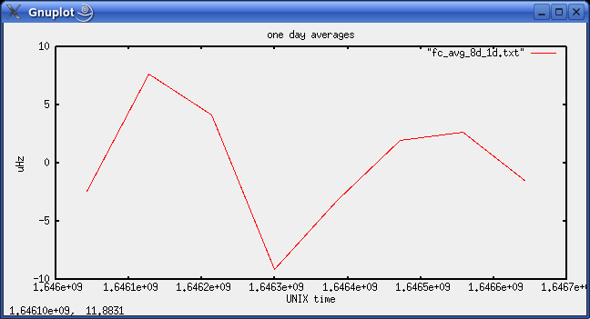
Fig 4.1.1.8
These stay within +-8uHz, therefore it should be possible to discipline the rubidium to better than 1E-12.
