A simple circular polarizer for 10GHz
Marko Cebokli S57UUU
(EME conference 2006, Germany)
ABSTRACT: A simple polarizer based on Ku-band satellite TV hardware
(orthomode couplers and feedhorns) and a dielectric delay plate,
suitable for 10GHz EME is described. The main goal was a no-tune
design that can be easily reproduced without measuring equipment, but
still achieves high quality (<1 dB axial ratio) circular polarization.
1. INTRODUCTION
For a long time, the only serious argument against use of circular
polarization for EME has been that, for a typical radio amateur, it
is difficult to achieve good circular polarization. This was based
mainly on the experience with screw polarizers, which indeed require careful
tuning with suitable measurement equipment, and linear orthomode
plus 90 degree hybrid combinations, where the connecting cables have
to be made with high precison and are prone to losses etc.
However, a few years ago, when Zdenek OK1DFC introduced the septum
polarizer to the amateur radio Moonbounce community [1], this changed
dramatically. Now everybody with moderate metal working skills
(cutting sheet metal to measure and joining a few such pieces) could
build a working no-tune circular polarizer, with separate ports for
left and right hand circular polarizations.
Later, CT1DMK presented another all-metal polarizer, a no-tune
variant of the "squeezed tube" type (metal inserts instead of
squeezing) [7].
While the septum can still work perfectly on 10GHz and higher, the
dimensions become a bit small for precise cutting with hand tools.
So for a long time I had the idea of using Ku-band satellite TV
components like orthomodes, feedhorns etc. and design a feeding
system based on them. At the 02 EME conference in the Czech republic,
SM6CKU gave me an orthomode/feedhorn combination and I promised to
design a polarizer for it.
2. TRANSITION - POLARIZER - FEEDHORN...
There seems to be a widespread confusion among HAMs about what is
a "dish feed"!
Most published "recipes" are in fact what should be
called a "feeding system", because they join together several
independent components. In a well designed feed, these should be
independent of each other.
There is no such thing as a "septum feed"! We only have a septum
polarizer, which can be used as a part of a CP feeding system.
For example a linear polarized VE4MA design combines three parts:
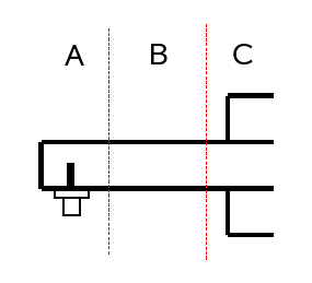
FIg 1. The VE4MA feed: A = transition, B = waveguide, C = radiator
First comes the coax to waveguide transition "A", which must bring
the EM wave from the coax cable into the waveguide in a well
matched way. This is its only task - in a well designed feed it has no effect on
the directional pattern. Another way of bringing the wave into the
round waveguide could be used here (for eample a rectangular/round
WG transition) without affecting the pattern.
Then comes a section of waveguide "B". On first sight, this does not
seem to be important/necessary, but it serves to supress any
higher modes that could have been launched by the probe in the
coax/WG transition. Such modes could distort the radiation pattern
of the feedhorn, if they would arrive at the aperture.
The attenuation of below-cutoff modes in a waveguide is extremely
high, so a very short section is enough to prevent this from
happening. It is the task of this section to assure that the
coax/WG transition and the feedhorn are really independent of each
other. In a well designed system, its length should not be
important, provided it is long enough to kill the higher modes.
However in HAM practice, there usually is
some interaction among the parts. Most often, the radiatig
section is not well matched and some reflection happens there.
This is usually compensated by detuning the coax/WG
transition. In this case, the length of the WG section is important,
since the reflections at the transition and aperture must cancel
out.
And last but not least, comes the radiating structure "C", the real
feedhorn, in the VE4MA case a parasitically excited coaxial resonator.
This determines the radiation pattern of the feed - and the pattern
will be always the same, regardless of how you have excited the
(fundamental mode) field in the waveguide.
Again, a
different radiating section (for example W2IMU) could be used
here to get a different pattern.
Even with a "coffee can feed", there is a "radiating
section" which can be treated separately, namely its aperture.
For a circular polarized antenna, we have to add another
component, the polarizer:
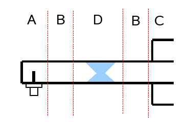
FIg 2. A circular polarized feed: A = transition, B = waveguide, C = radiator,
D = polarizer
Again, in a well designed system this component should be
independent of the others, so any type of polarizer can be
used with any type of radiator. (The original OK1DFC version
of septum has square waveguide output, so another component,
a square to round transition, must be added if standard
feedhorns based on round waveguide are to be used.)
3. Ku-BAND SATELLITE COMPONENTS
Modifying Ku-band LNBs into 10GHz low noise preamplifiers has a long
tradition among microwave HAMs. But there exists a whole bunch of
other Ku-band components often available for cheap at fleamarkets
and general junk, that could be abused for HAM purposes on
the 10GHz band:
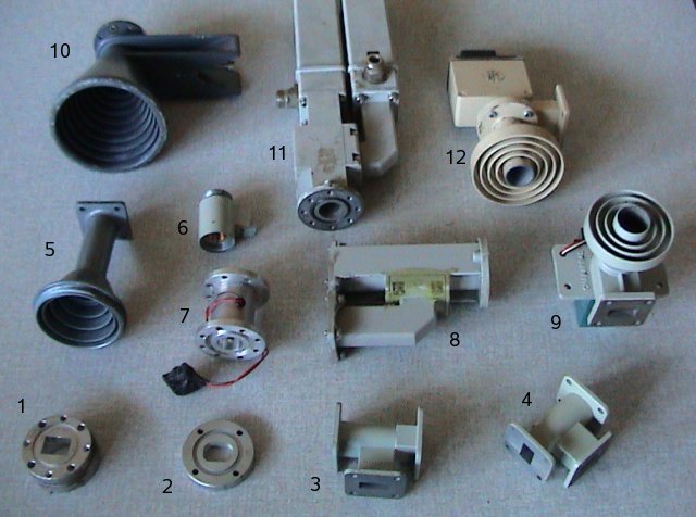
FIg 3. 1 = two stage rectangular/round transition; 2 = single stage
rectangular/round transition; 3,4,8: linear orthomode couplers;
5: feedhorn for offset dish; 6,7: ferrite polarotors; 9,12: mechanical
polaotors with feedhorns for central fed dish; 10 feedhorn for Gregorian
system; 11: linear orthomode with two LNBs.
They all use R 120 (WR-75) rectangular and 19mm diameter round waveguides.
(Strangely, this is not a standardized size for round waveguides! For example C104 (WC80) for 10-13.7GHz is 20.24mm and C120 (WC69) for 11.6-15.9GHz is 17.475mm)
The idea here is to use a satellite linear orthomode coupler and add
a simple circular polarizer. This way we get a circular ortho, with
two separate R 120 ports for left and right hand polarization.
4. THE DIELECTRIC PLATE POLARIZER
A circularly polarized wave can be thought of as two linear polarized
mutually perpendicular (for example, at + and - 45 degrees) waves with 90 degrees of phase offset:
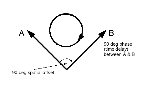
FIg 4. Making a circular wave from two linear ones
A (for example) linear vertically polarized wave can also be thought
of as a sum of two perpendicular linear waves at + and - 45 degrees,
but with zero phase offset:
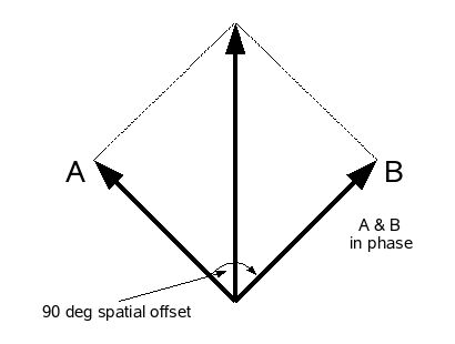
FIg 5. Making a linear wave from two linear ones
Looking at the pictures above, one can easily see that all that has
to be done to change fig 5 into fig 4 (linear into circular) is to
delay one of the 45 degree components 90 degrees in phase, relative
to the other.
There are several ways to achieve this, for example two rows of screws
at 45 degrees, or a waveguide that has different dimensions (and hence
different propagation speeds) in the two 45 degree planes - a squeezed
tube [2].
Another way is to load the waveguide with dielectric in a suitable way,
for example by putting a sheet of dielectric material into the waveguide
at a 45 degrees angle to the incoming linear polarization [3].
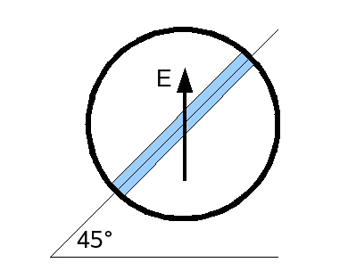
FIg 6. A dielectric plate polarizer (blue) in a round waveguide
Doing this, one has to be careful not to cause too much reflections
in the waveguide. An old rule of waveguide plumbing says: do things
gradually to reduce reflection. Following this rule, the dielectric
plate is shaped like this:
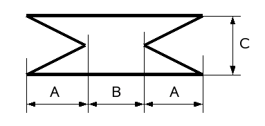
FIg 7. The shape and dimensions of the dielectric plate
Of course the dielectric material used must be of low loss at the
operating frequency. First thing that comes to mind is PTFE, but it
is soft (doesn't keep shape very well) and it is hard to glue into
place. I did first experiments with PTFE but then changed to PMMA
("plexiglass"). Loss wise it is no worse than PTFE (negligible losses
in both cases), but its hardness is "just right", easy to cut and
file while stable in form. Easier to glue, too.
I've designed the 10.4GHz version to fit into the 19mm round
waveguide used by the satellite TV industry. Individual pieces
will differ in diameter by a few tenths of a mm. I suggest filing the plate
so that it fits tightly, this way it might not even be necessary
to glue it in.
On the feedhorn given to me by SM6CKU, the bore is somewhat conical,
(a requirement of the casting / molding process?) so the plate
nicely "wedges" into position.
I made the plate by first cutting it out with a jigsaw, making it
slightly bigger than required, and then filing it to measure.
The dimensions for 4.3mm thick PMMA are A=16mm, B=11mm, C=19mm. To get better than
1dB axial ratio, the tolerances should be within 0.5mm - not too hard
to achieve. Drawing a template on mm paper can help here.
The 45 degree angle at which the plate has to be placed into the
waveguide is quite critical, should be within a couple of degrees.
5. RECEIVER PROTECTION
The R 120 flange on the satellite ortho is ideal for a modified LNB
type preamplifier. However, the isolation between the ports is
typically around 20dB, not enough to protect the LNA from the
EME transmitting power levels.
A simple zero-loss receiver protection switch can be made by simply
inserting a metal pin into the RX waveguide using a spring loaded
solenoid coil:
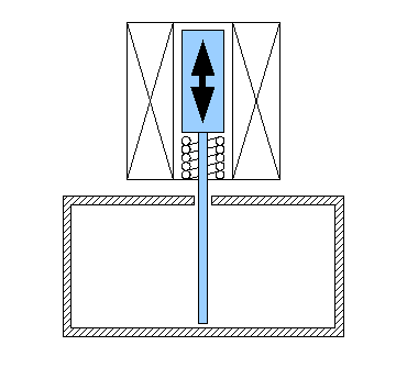
FIg 8. A simple way to protect the receiver
Solenoids from old relays, washing machine valves, etc can be used.
20..30dB can be achieved even without the probe having contact
with waveguide walls.
Together with the port isolation, this gives a comfortable margin
for receiver protection.
6. BUT I HAVE HEARD THAT CIRCULAR POLARIZATION IS WORSE FOR EME...
There were rumors of this kind circulating around the EME community,
but they aren't true.
In my paper at the 2000 EME conference in Rio [4] I have described at
length why circular is better.
At that time I did not yet know
about the differential depolarization at the Moon, so let's
take a look at that.
Luckily, WA5WJB has put some hard to find old lunar radar papers online
(most relevant is [5]), so we can see what empirical measurements
have shown.
When superficially looking at these papers (for example seeing figure 4
in [5] without reading the fine print below it) one can really get the
false illusion that there is a problem with circular.
But reading them carefully, going through the math and numbers, one
can see that this is not the case.
So, in short, what can be concluded from these papers?
Relevant for our discussion are the differences in depolarization
between linear and circular, which are described there.
As can be seen from figs 5 and 7 in [5], this happens predominately
at the outer rim of the lunar disk, where the incidence angle is
above 45 degrees (cos < 0.7 in the above mentioned figures).
In that area the polarization ratio is cca 7dB (83% vs 17%) for linear
and 3dB (50% vs 50%) for circular. This means 0.8dB of loss for
linear vs 1.8dB for circular. That would be a 1dB advantage for
ALIGNED linear (I've shown in my Rio paper [4] that in a typical EME
situation, polarization is almost never aligned, causing on average
more than 1 dB of loss).
But these numbers hold only for the outer limb of the Moon, which
only contributes a small part of the echo.
Integrating the 3.8cm numbers in table 1 from [5], (see spreadsheet [6])
one can see that this outer part (>45 degrees) contributes only cca 20%
of the total returned echo.
Weighing the depolarization curves in figs 5 and 7 of [5] with the
values from table 1 from the same paper, one can estimate that the
effective depolarization
ratios of the whole Moon are cca 9.5dB (89% vs 11%) for linear and
8dB (86% vs 14%) for circular. This is 0.5dB vs 0.65dB loss for
linear and circular, respectively.
This means that the "circular depolarization penalty" is only 0.15dB!
Obviously, the "circular depolarization penalty" is
significantly smaller than the "linear nonalignment penalty",
as I described my Rio paper.
And more than that, the 0.15dB signal deficit is of the diffuse
part from the rim, which contributes most of the Doppler broadening!
This means that the "good signal" (specular part from the center
of the lunar disk) vs "bad signal" (Doppler broadened diffuse part
from the rim) is BETTER for the circular polarization!
This was also confirmed by amateur experiments [7].
In the linear scenario, when the polarization is not aligned,
there is not only signal loss, but the "good vs bad" signal
ratio will deteriorate further, because the "good" polarized
part from the center wil decrease, and the cross-polarized
contribution from the rim will increase! So any misalignment will
cause a further increase of Doppler smear (spectrum broadening)!
Ergo: IT MAKES A LOT OF SENSE TO USE CIRCULAR POLARIZATION FOR 10GHz EME!!
7. CONCLUSION
Being a very lazy person myself, I can understand that people who
have working linear systems are reluctant to make modifications on
them, therefore they do not like the idea that others would go circular.
However experimenting with and modifying our hardware should
be a part of the hobby, shouldn't it?
Personally, I have both linear and circular feeds for my dish, so I have no vested
interest here. But from own operating experience, I know that linear stinks...
8. REFERENCES
[1] Zdenek Samek, OK1DFC: Information and practical hints for the
    construction of a septum feed  DUBUS 2003 I/39

[2] W2IMU  Carwford EME notes
    Available online at:
    http://www.ve1alq.com/W2IMU-K1RQG/w2imu_notes.html


[3a] Antenna Engineering Handbook, second edition, Eds R.C.Johnson, H Jasik,
     pp 23-20...23-23

[3b] Antenna Handbook, theory, applications and design,  Eds Y.T.Lo, S.W.Lee,
     pp 21-29...21-30

[4] Marko Cebokli S57UUU: Let's go circular on 10
    9th EME conference, Rio de Janeiro 2000
    Available online at:
    http://lea.hamradio.si/~s57uuu/emeconf/ltsgocir.htm

[5] Tor Hagfors: A Study of the Depolarization of Lunar Radar Echoes
    Radio Science, Vol. 2 (new series) No. 5, May 1967
    Available online at
    http://www.wa5vjb.com/moon.html

[6] http://lea.hamradio.si/~s57uuu/emeconf/eme06.ods

[7] Luis Cupida, CT1DMK: Circular Polarized Antenna Feed - for EME
    on 10GHz and 5.5GHz.     DUBUS vol 35 no 2  May 2006, pp  22...33
Up to S57UUU Home Page
Copyright info


