It's main advantages are:
- >80dB dynamic range - no fiddling with attenuators to find diode's 'sweet spot' level
- three ranges: full, 10dB and 2dB
On the 2dB scale, it is easy to see a few hundredths of a dB change, anywhere within the cca -70 to +10 dBm range.
The AD8307 is specified DC-500MHz.

C1 and C2 should be chosen according to the input frequency. Together with the cca 1kohm chip input resistance they make a highpass filter. For 144MHz a value between 100p and 1n works OK.
R1 is for the 'full' range (80..90dB), around 390ohm. Use a trimmer if you need precise scale calibration.
R2 is for the 10dB range, around 3K3. Use 4K7 trimmer if required.
R3 is for the 2dB range, cca 18K. Use 22K trimmer if required.
R4 depends on the meter used, it should give full deflection for 4V across meter+R4. If the meter's current for maximum deflection is Im and it's resistance is Rm then R4=4/Im-Rm. I had Im=1mA and Rm=100ohm, so R4 was 3K9 in my case.
The opamps used must have input common mode range down to zero, like LM324 or LM358.
The top amp (A1) provides amplification for scale expansion, and the bottom one (A2) provides an adjustable 'elevated ground' to enable any part of the 80dB range to be expanded.
Q1 is any small NPN transistor like BC108 or 2N2222. It is needed because LM358 cannot pull the output all the way down. If you have an 'rail to rail' opamp (watch the input common mode range!) you can remove Q1 and the 220 ohm resistor. In this case, dont forget to swap the opamp inputs!
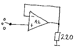
Another way is to 'help' the LM358 opamp reach ground with an resistor like this:

Note the swapped inputs. You should be able to reach down to at least below 0.2V on the opamp's output under full meter current. Turn the potentiometer all the way down and check with an voltmeter.
A2 is switched between a fixed offset for the 'full' range and a variable offset for the expanded ranges. Use a multiturn potentiometer for precise setting of the offset.
One thing I found important is good shielding, filtering and decoupling. This is a very sensitive broadband circuit, it can be driven crazy by leakage of local AM radio or cellular thru the supply line.
If you're using it after an converter/transverter, LO residuals and (sub)harmonics can cause problems too. So it is a good idea to provide a small 144MHz bandpass on the input, just a tuned circuit or two, since the AD8307 will see anything from DC to more than 500MHz...
I think this AD8307 is among the best things that could happen to a RF hacker...