High Performance Antenna Stack for 2m Contest&Tropo Work
1. Few words regarding the 2m contesting in EU
Every serious 2m contester must have came to one of the main technical questions - what kind of the antenna is the best antenna for my contest location! One would quickly give an answer - the one with as much gain as possible. This answer is correct only for those stations that are located far away (800 km and more) from main activity areas. The main activity areas are certainly DL and OK and then spreading out from center of EU. When the contest location is such that important QSO's (the ones that bring a lot of points, that is the ones with high NrQSO*QRB product) can be made into many directions there comes into the first plane the 3 dB main lobe angle of the antenna used.
Fig. 1: QSO pattern diagram for a typical S5 VHF contest location.
This picture shows the more or less standard QSO pattern diagram for a typical S5 contest location (Alps into the 300 deg. direction, Balkan mountains and Adriatic sea into the 120-180 deg.). From the statistics on the left side of the picture one can see that about 60% of points are gathered from the three directions with the antenna that has 30 degrees of azimuth angle (that kind of statistics can be calculated with VHFSTAT.EXE program if the QSO data is available in the EDI format - one must transform the EDI format into the QSO/TST format with VHFLIB.EXE). From this chart one would conclude that it would be good to have two antenna systems - one with 30 deg. and one with 75 deg. of antenna angle. At this point comes into the question the interference caused by nearby stations when using an antenna with 75 degrees. It is important to use high dynamic range RX (that excludes the preamplifiers, of course). The best would be the home made RX but the XVRT+HFRIG configuration with the target system noise figure of about 2.0 dB is also OK. The system noise figure (the cable loss plus RX NF) should not be below 2.0 dB as the gain of the XVRT must be increased and that goes directly into the conflict with high dynamic range wishes (turbo deluxe XVRT and super HFRIG are transformed into the medium class RX when an even ideally linear preamplifier with 15 dB of gain is added in front of them!).
So the common solution is to install two or more antenna systems. To be efficient the second (third etc.) antenna system should equal in performance to the main antenna system (equal gain and power to +/- 3 dB). When using more than two antenna systems the normal RX/TX setting (that is one TX with power divided between two antennas and one RX switched between two antennas) is no more an optimum solution. Time to switch between three or more antennas becomes too long and one can completely miss the call sign. At least two independent RX's are needed for efficient use of 3 to 4 antenna systems (together with the second operator, of course). If all the RX operators can also transmit that would be the best solution but this is not really needed.
The minimum antenna gain for tropo contest is about 16 dBi. This gain can be delivered by the 4 lambda yagi, but the 3 dB azimuth (E plane) angle is less than 30 degrees. So how to get the 50-70 degrees of azimuth coverage and more than 16 dBi of gain? The answer is the I-stack of short yagi antennas.
2. I-stack of four 4 el. max. gain yagis
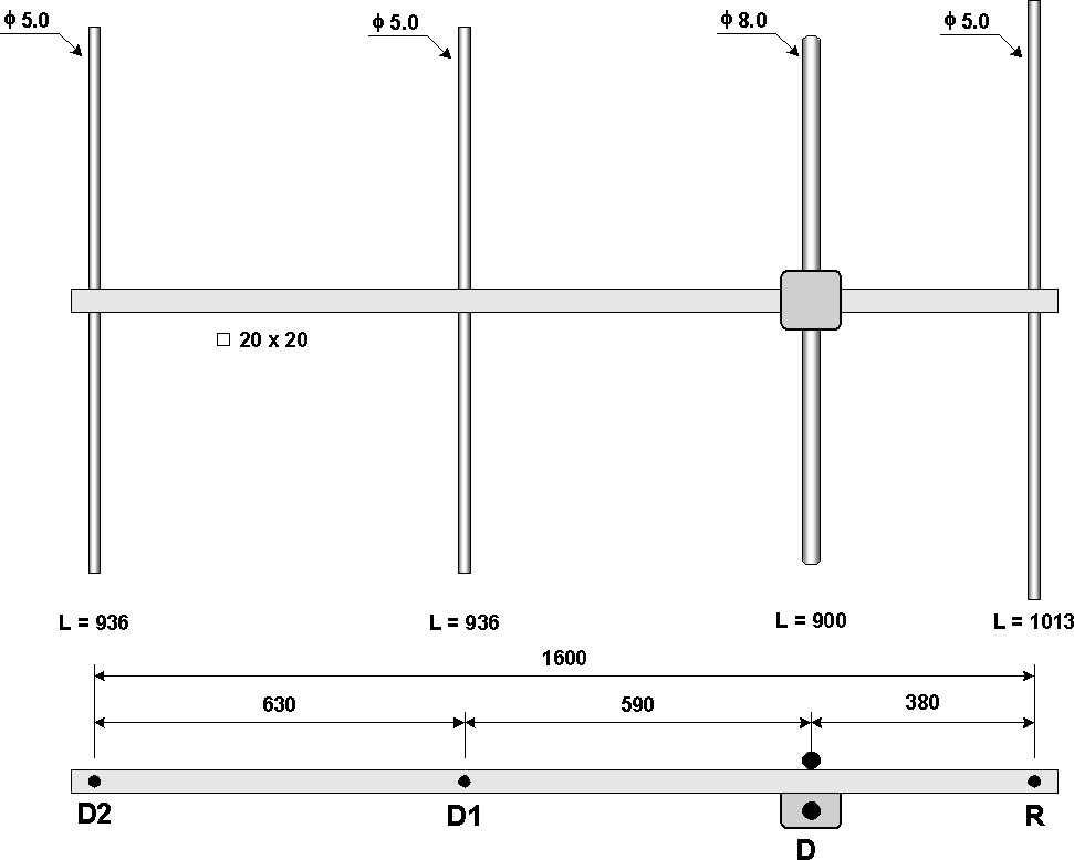
After careful inspection of our contest location (S59DEM/JN75DS) QSO pattern diagram I decided to build an I-stack of four short yagis that will have 3 dB main lobe width of 50 degrees. With four elements one can get the required 50 degrees. To get all the available gain I chosen the maximum gain yagi design. Maximum gain can be obtained when the antenna impedance is less than 50 ohms. Fixing the antenna impedance to 12.5 ohms one can get the 50 ohm antenna with a folded dipole and simple choke balun. In that manner one can build the antenna that has 50 ohm input, 11.3 dBi of gain, 50 degrees of E plane main lobe angle and 1600 mm (0.8 lambda) length (see the Fig. 2 for technical details). The simulated E- and H-plane and measured E- and H-plane patterns are shown on the corresponding pictures.
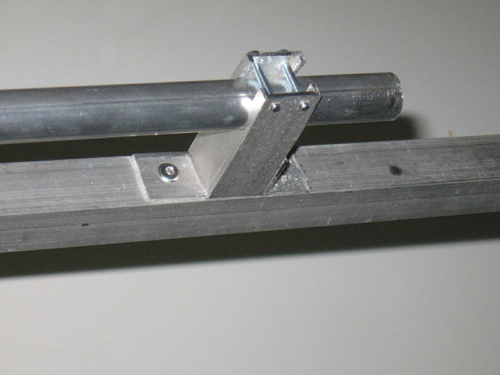
Fig. 2: Four element maximum gain yagi characteristics with stacking gain of two antennas versus vertical separation. Boom is made of 20x20 mm square Al tubing. Elements are made of 5.0 mm diameter aluminium rods and are isolated from the boom (boom correction is 2.0 mm). Plastic caps (home furniture parts) were used as insulators for the elements (see details on the photographs). As this technique did not prove to be mechanically rigid enough, the elements and insulators were later glued to the boom with the two component glue.
The only drawback of the short maximum gain yagis is narrow bandwidth (144 - 145 MHz for 1:1,5 SWR) and poor front-to-back ratio (i.e. 12.5 dB for the current design). As the antenna was not intended to be used alone the F/B ratio problem can be efficiently solved with proper stacking scheme. Proposed stacking scheme also improves the SWR of the whole stack because of reactive compensation (1:1 SWR across 143 to 146 MHz). Individual antennas should be horizontally offset by lambda/4 and fed with correct phase. In that way one can get something like 25 dB to 30 dB of F/B ratio (simulated E- and H- plane pattern). It should be pointed out that the back lobe is cancealed at the E-plane only - it is split into two vertical backlobes as can be seen on the simulated H-plane pattern. The vertical offset scheme is shown in the Fig. 3.
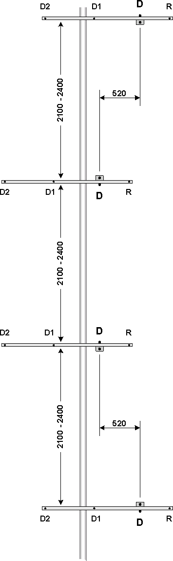
Fig. 3: Dimensions of the I-stack of four 4 el. yagis. Note that the vertical separation is 2.1 m minimum and can be increased to 2.4 m with 0.1dB/0.1m of gain increase. On the upper sketch one can see the positions of the vertical mast / boom crossing. The upper and the lower antennas are attached to the vertical mast between the D1 and D2, and the middle antennas are offset for 520 mm into the forward direction. Because of that the cables feeding the middle antennas should be electrically lambda/4 longer (it means that the cables should have length of 520mm*velocity_factor longer (340 mm for solid PE dielectric cables and 360 mm for solid PTFE)).
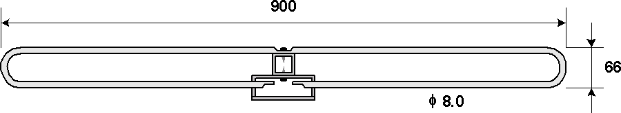
The dipole (see Fig. 4) is a classical folded dipole with the same dimensions as per DJ9BV antennas but with the length of 900 mm and the balun is of a choke type made from RG-188/RG-316 coaxial cable (see Fig. 5). Dipole is attached directly to the boom (dipole tubing is pressed in the middle across the length of 25 mm, a hole is then drilled through this flat portion of the dipole tubing and boom - dipole is then fixed to the boom with appropriate screw. The same technique is used for connecting the balun to the dipole).
Fig. 4: Folded dipole details.
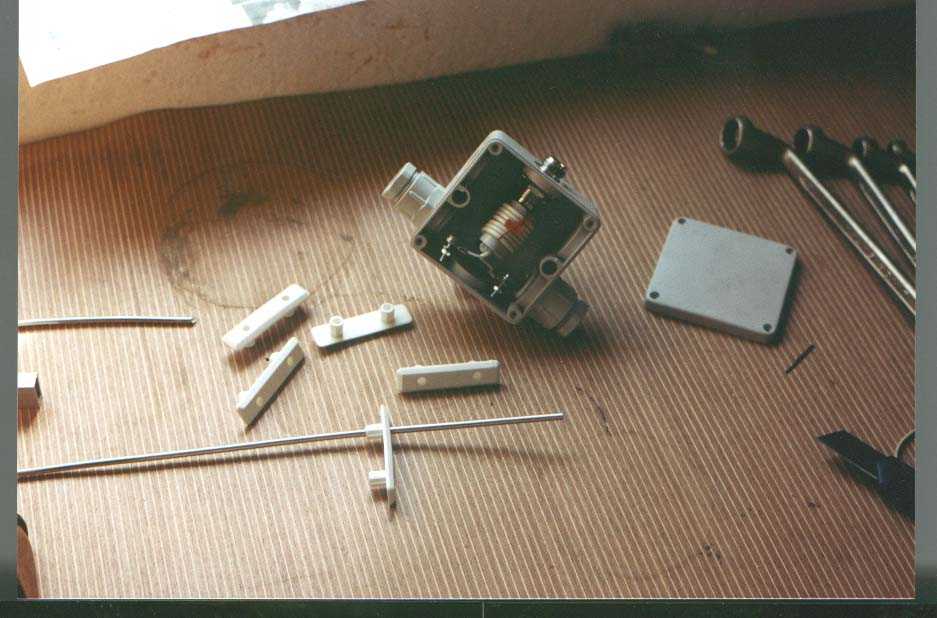
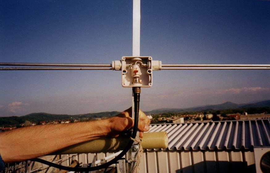
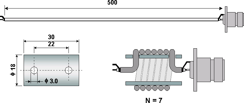
Fig. 5: Choke balun details: the 7 windings choke is wound from 500 mm long thin teflon cable (i.e. RG-188) on the plastic form of 18 mm diameter (plastic pipe used for house installations) with pre-drilled holes 22 mm apart that serves for cable fixing. The N-type connector for direct mounting to the RG-188 is used.
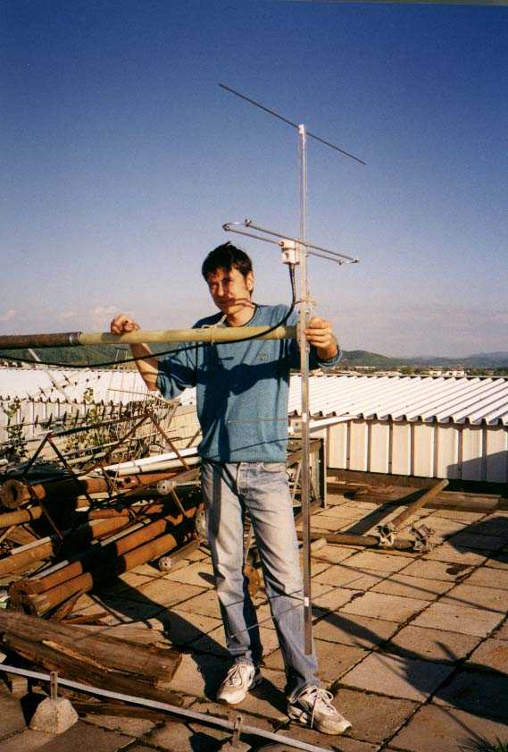
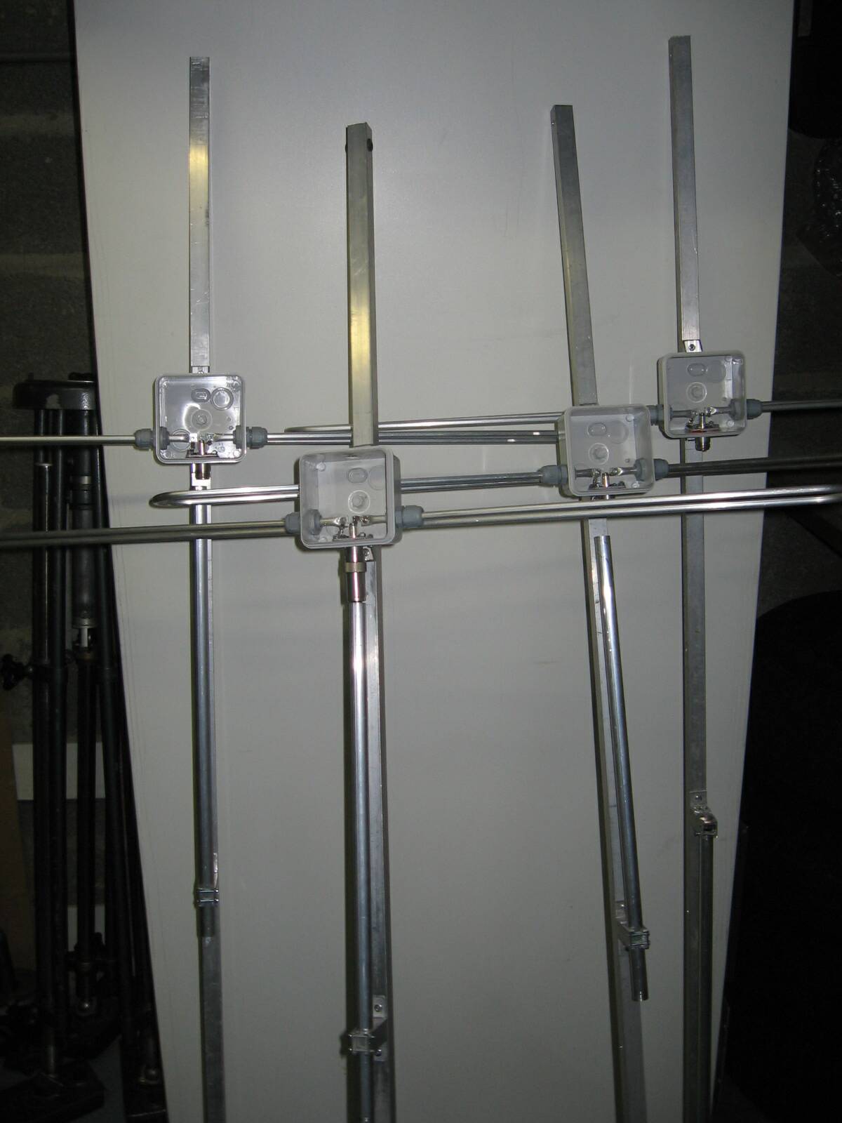
The complete balun is housed in the plastic housing as used for electrical installations. The detail of the dipole with the balun is shown here and the author with the antenna at the Ljubljana Faculty of Electrical Engineering antenna measuring site can be seen here.
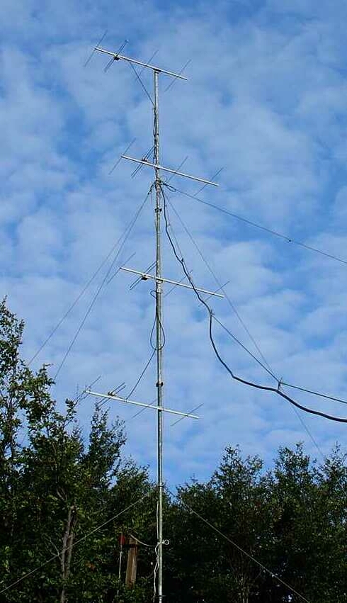
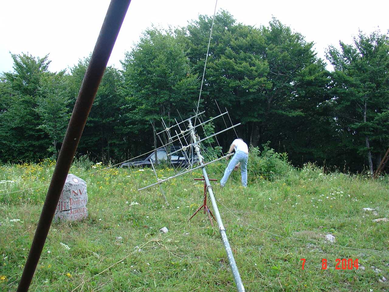
Fig. 6: Photograph of the built 4x4 el. yagi antenna at the JN75DS location (V. Javornik, 1269 m asl).
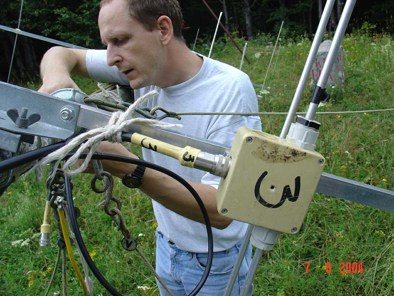
The antenna stack proved in the contests (S59DEM/S55AW/S53WW) for the last two years as very good as compared to a single 15 el. DL6WU. Our main antenna system that is composed of two 15el. DL6WU stacked vertically has around 3 dB higher gain (the 4x4 has longer cable run (about. 0,5 dB) and only rg-213 stacking cables (we use the stacking cables of our old 4 x 6 el. system)). Here you can see Stanko/s55aw mounting antenna No.3 to the cable No.3 and all four antennas just before raising them up.
Here are some nice schematics of the whole design (TNX to Romi/s57pr) - antenna, balun, dipole, stack.
Last modification: 01.09.2002
Some patterns, pictures and text added on 20.09.2004.
Very important correction added (TNX to S52SR) - see Fig.3 - on 22.03.2005.
Added on 22.10.2006:
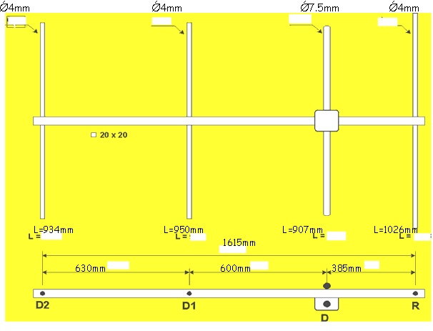
F5IGK/Alain reproduced the antenna stack with 4mm/7,5mm element diameters. His dimension of the element lengths can be seen here.
Alain used bazooka type baloon instead of proposed cable coil. This is a very good solution. The sleeve is made of 12mm Al. tube (inside diameter). When using RG214 as feeding cable, the length of the tube should be 400mm. Shorting stub to the boom is 385mm away from connector end of the sleeve. Some pictures can be seen here - sleeve, antennas, dipole. Check also this link http://www.w8ji.com/sleeve_baluns.htm.
---------------------------------------------------------------------------------------------------------------------------------
Added on 12.05.2007:
This year we had to change the phasing cables - the old ones were more than 15 years old and had some bad contacts ...
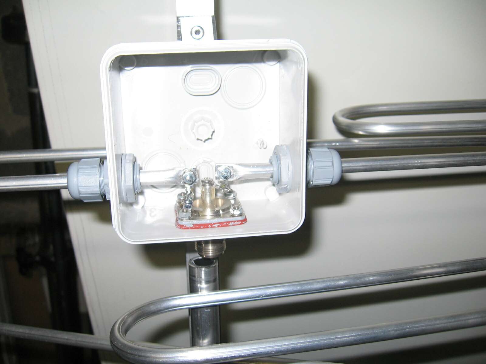
So I prepared cables with optimized lengths as can be seen on the picture. I used RG214. The cables are joint together as a simple T junction (unfortunately I forgot to took a picture of those junctions). Junction is made from copper tube T-junctions that are used for hot water installations (plumbing) . So no extra connectors were used - only 4 connectors for the dipoles and one for the shack cable. One can use ordinary N type T-junctions instead.
So to clear all the doubts: two antennas are connected in paralel to
get
25ohms; then lmb/4 of 50 ohm cable is used to transform those 25ohms to
100ohms;
one gets 100ohms from the other antenna pair too; then those two
100ohms ends
connected in paralel give 50ohms. Please note that lmb/4 transformer is
of
7*lmb/4 length (238cm).
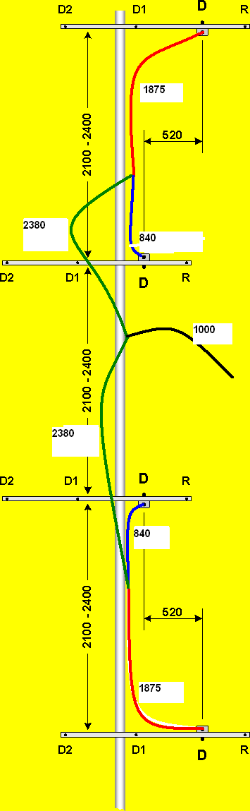
Take care about the proper differences in cable lengths to maintain the
right phasing! So "red" and "blue" lengths must be as close to the same
value as possible,
and also the difference between red" and "blue" must be the same - it
means, that if "blue"
is cut to 860mm instead of 840mm, then the "red" must be cut to 1895mm
instad of 1875mm!