XTAL-box-14M
1. Introduction
As the main problem in dense areas of many well equipped VHF
contest teams appears to be TX noise originating in HF RIG a
possible solution to this problem is TX IF preselector.
Although the main motivation for this project was HF RIG TX noise
reduction, the IF preselector
brings tremendous benefit on RX as well. Just imagine the
"crazy" situation when the XVRT TX driving signal going out of HF RIG
can be 20 dB lower than the RX IF signal going from XVRT into HF RIG
receiver (50 km LOS, 2x 1kW and 17 dBi antennas pointed one to other
==> 10 mW signal level that enters HF RIG receiver, while XVRT
drive signal is in the 0,1 mW range).
The preselector also has a major role in setting
up an efficient remote RX system (RX system 50 ...
200 meters away from main TX antennas that can be
used during transmit time).
More
about this was said at regular S5
VHF&up meeting in Nemčavci 2011 (also available in Czech
- tnx to OK1UBO) and by other hams many many years ago (i.e.DL7QY in
1987).
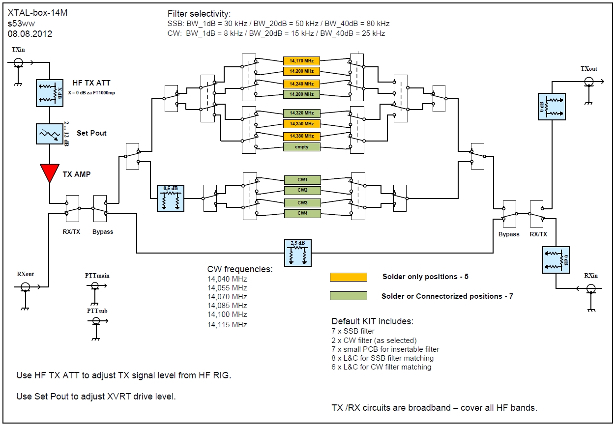
2. Block Scheme
Block sheme is shown on the diagram below and is very similar to the
older project by Vlada/OK1VPZ.
2. Results
After more than 10 units tuned it can be said that the filters are
of a very high quality and very repeatable - i.e. insertion loss of
different filters and between different units is below +/-
0,2 dB.
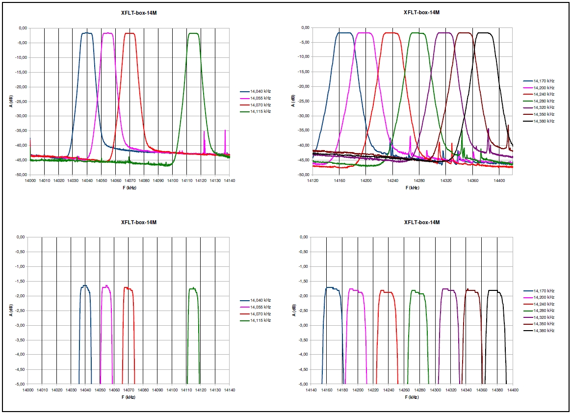
Photo of a prototype unit (as tested in AA VHF 2012 and IARU
VHF 2012 by S59DEM).
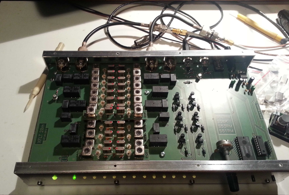
Photo of a final unit - front view (Pout potentiometeer on the
left, positions marked with star are pluggable, filter selection
buttons on the right).
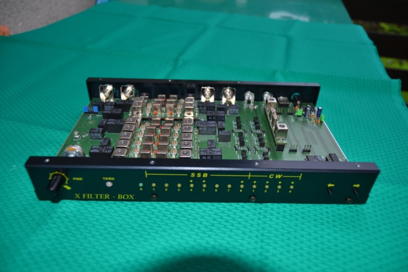
Photo of a final unit - rear view (DC, remote buttons and PTT
connectors on the left).
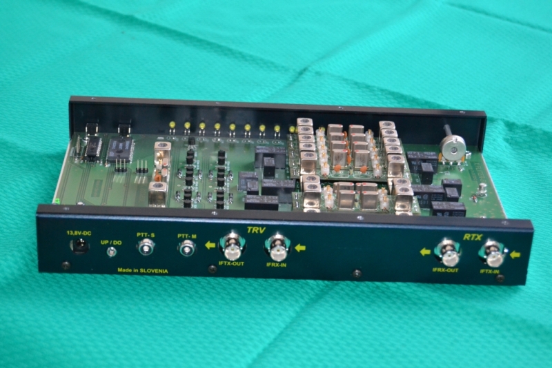
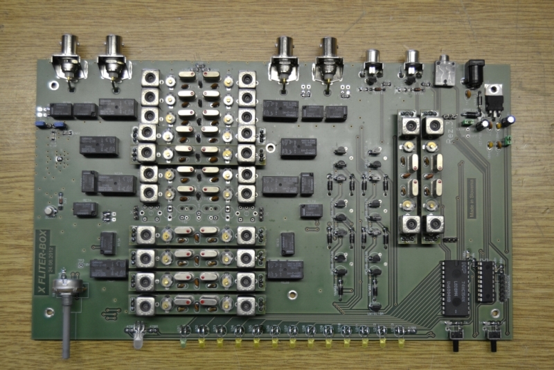
Photo of a final unit - top view (two pluggable filters on the
right are in the "parking" positions).
3. Specifications
RX:
- Insertion
Loss: 1,8 dB ± 0,2 dB
- P1dB: >+13 dBm
TX:
- Gain:
10
dB (at 0 dB HF ATT)
- Gain
regulation: 10 dB max
- Pout
nominal: +1
dBm (at 0 dB HF ATT)
- OIP3: +23
dBm
- IMD3
/ 5 / 7: -46
/ -72 / -90 dBc (at Pout 0
dBm)
General:
- Power
supply: 13,8 V
- Consumption: 300
mA max
- Dimensions:
275 (W) x 163 (D) x 40 (H) mm
4. Construction
Design is pretty straightforward and in accordance with KISS
principle.
Schematic: IF TX/RX, PIC, XFLT, RELAY
PCB layout: TOP,
BOTTOM
Photo of a pluggable filter PCB.
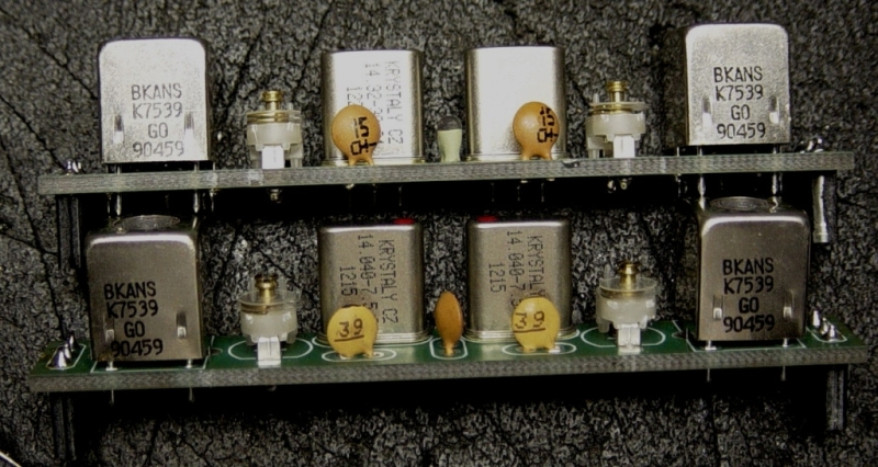
Crystal filter datasheet (made by http://www.krystaly.cz/en/): SSB, CW
PIC program listing and HEX file.
Last minute schematic correction: the gate of both PTT BS170 FETs
should be connected to the ground via 100k resistor (can be easily
soldered on top of 1n capacitor).
5. Description and Operation
Preselector
has 13 filter selectrions: 8 for SSB filters, 4 for CW
filters and one bypass. It is used on TX as well as on RX.
Insertion
loss is less than 2 dB so it does not have significant
impact on receiver sensitivity. Beacuse filters protect HF receiver
from very strong signals the preamplifier on the HF RIG can freely be
swithed on (AIP OFF on
FT-1000mp). Preamplifier has to
be switched on in case we add
additional losses on the IF RX line (i.e. antenna IF switch matrix) to
maintain required sensitivity of the complete receive system.
PIN
attenuator and high dynamic range IF amplifier are placed in front of
filters in the TX path. PIN attenuator functions as main output power
setting control. TX amplifier replaces the IF TX AMP in the
Javornik-144/14 XVRT. This means that IF TX AMP in
XVRT needs to be switched off (position of jumpers J2, J3 and
J4 need to be changed). By doing so about 6 dB lower TX noise of
the XVRT can be achieved. Nominal TX level out of preselector
is +1
dBm. This level is high enough to drive two XVRTs in parallel up to
about 30 W (XVRT Pout potentiometer fully open!). In case output
power from XVRT is not high enough the missing gain should be
obtained by changing PI attenuator between BFG196 driver and power
module (default 11 dB for 60W version) and NOT by switching-in IF TX AMP.
Two PTT
signals can be connected to the preselector, »main«
and »sub«. »PTT main« is normal PTT
function – it switches both RX/TX relais. »PTT
sub« function is supporting more advanced contest setups with two
HF RIGs, where the second RIG (»sub«) is used for
S&P. The »sub« RIG will be
mainly outside the »main« RIG filter
passband so »PTT sub« also switches »bypass
relay« beside RX/TX relais. This way any transmission
with »sub« RIG will always bypass filters.
Filters
can be selected by two push buttons on front panel ( ← and →). Remote push
buttons can be connected to the 3.5 mm stereo jack on the back panel.
It makes sense to assemble 3 push buttons on a small PCB with long
enough cable so that such a small control PCB can be freely
positioned on the desktop area. Third, the middle, button
should connect both signals to the ground in parallel - pictures
below are self explanatory. Pressing middle
button selects bypass position - pressing it again returns to the last
selected position. It turned out that the middle button is being
the most pressed button during the contest operation.
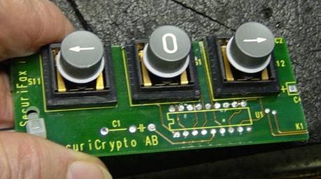
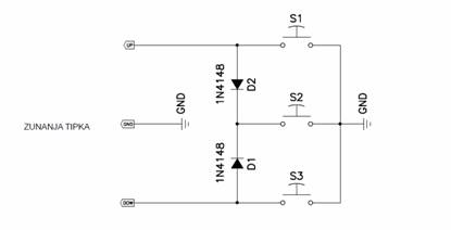
Remote filter
selection buttons
HF TX ATT (see
block scheme) value depends on the HF RIG in use. Install 0
dB for FT-1000mp.
Nominal TX input level is between -9 dBm and -11 dBm. In case HF
RIG provides higher TX level, the difference needs to be leveled
out by HF TX ATT. Example: TS-850 XVRT TX level is +10 dBm
-->
HF TX ATT value needs to be 20 dB.
How
to set TX chain levels:
- optimal
output power of 25 W Javornik version is 5 ... 25 W, and 5 ... 50 W for 60 W version; higher
IMD levels (splatters) are created by pushing it to higher output
powers; higher TX noise is produced when transmitting with low
output powers. In case PA that follows XVRT needs less than 5 W of
drive level use power attenuator at the XVRT output to reduce the
power.
- fully
open PIN attenuator
- set
PA
output power with potentiometer in the XVRT (i.e. 500 W)
- use
PIN
attenuator to reduce the level by 1 dB (i.e. from 500 W to 400 W)
- set the
output power to the previous level with potentiometer in the XVRT (i.e.
back to 500 W)
- PIN
attenuator has now very fine output power control; it can be increased
by 1 dB (+25%) or reduced by about 8 dB (6 times).
6. "Measurement day" results
On 15th December 2012 we organized a filter tuning and TX
signal quality measurement day in Ljubljana. From far it looked like a
"FT1000mp
fan club" meeting :) Some photos can be seen here.
We had 15 HF RIGs on a test bench, about the same amount of
Javornik-144/14 XVRT and XTAL-BOX-144M and three solid state 2m kW PAs.
Event was visited by 23 S5 VHF contest enhusiasts.
The test results are summarized in the tables below. Please note
that the goal was not to perform very accurate measurements - it was
more on comparison and finding "hidden" issues (precision of the
results is probably not better than +/- 2 dB).
All the measurements were made with QS1r as a measurement receiver
(SDRMAX v5.0.0.8, 4096 FFT, 64 AVG, 0.125 Msps and 1.25 Msps); external
step atenuator
and low noise preamplifier were used to bring the test signal 1 ... 2
dB below QS1r clipping level to use its full dynamic range. QS1r modification enabled measurements
directly at 144 MHz (external 10 MHz wide bandpass filter was used).
6.1 Phase noise test results
| TX
phase noise - HF RIG @ 14200 kHz |
TX
sideband noise level dBc/Hz |
| |
20
kHz offset |
50
kHz offset |
200
kHz offset |
| FT1000mp (s53ww;
6K150120) |
-132,0 |
-134,0 |
-143,0 |
| FT1000mp (s53d;
3F480049) |
-130,0 |
-132,0 |
-135,0 |
| FT1000mp (s57q; 9H460108) |
-131,0 |
-133,0 |
-143,0 |
| FT1000mp (s57c;
0X123456) |
-132,0 |
-134,0 |
-142,0 |
| FT1000mp (s55m; 0E540077) |
-134,0 |
-136,0 |
-145,0 |
| FT1000mp (s50c;
2H070329) |
-134,0 |
-136,0 |
-142,0 |
| FT1000mp (s50c; 2H070329) @ ANT connector 5 W |
-123,0 |
-123,0 |
-123,0 |
| FT1000mp (s50c; 2H070329) @ ANT connector 100 W |
130,0 |
132,0 |
-142,0 |
| FT1000mp (s53v; 7I200025) |
-134,0 |
-136,0 |
-143,0 |
| FT1000mp MV (s59a; 41630092) |
-128,0 |
-130,0 |
-145,0 |
| FT1000mp MV (s57m; 1E270014) |
-134,0 |
-136,0 |
-143,0 |
| FT1000mp MV (s53d;
4L260088) |
-135,0 |
-138,0 |
-144,0 |
| FT1000mp
MV (s59r; 5L360040) |
-132,0 |
-134,0 |
-143,0 |
| TS590 (s52ei; B2700070) |
-132,0 |
-134,0 |
-138,0 |
| TS590 (s59p; B1400177) |
-132,0 |
-134,0 |
-138,0 |
| IC7600 (s50c; 0402264) |
-130,0 |
-136,0 |
-143,0 |
| IC7600 (s50c; 0402264) @ ANT connector 5 W |
-121,0 |
-121,0 |
-125,0 |
| IC7600 (s50c; 0402264) @ ANT
connector 100 W |
-131,0 |
-136,0 |
-143,0 |
| FT2000 (s50l; 7E190058) |
-127,0 |
-130,0 |
-133,0 |
I yellowed the values that are below 120/125/135 dBc/Hz @ 20/50/200 kHz
respectively (my arbitrary set limits). From the test results it
can be seen that FT1000mp and MV behave well and there is no much
difference between different radios. It can also be noted that driving
XVRT with TX signal from regular antenna connector with
reduced output power (to let say 5 W) should never be
used as the phase noise floor is degraded by about 13 dB (for 100
W to 5 W reduction as an example)!
| TX
phase noise - HF RIG + XVRT @ 144200 kHz |
TX
sideband noise level in dBc/Hz |
|
| |
20
kHz offset |
50
kHz offset |
200
kHz offset |
w/
XFLT |
| FT1000mp (s53ww; 6K150120) + XVRT(s50k/v1)@25W |
-132,0 |
-134,0 |
-138,0 |
-140,0 |
| FT1000mp (s53ww; 6K150120) + XVRT(s53rm/v2)@25W |
-131,0 |
-133,0 |
-137,0 |
-139,0 |
| FT1000mp (s53ww; 6K150120) + XVRT(s53rm/v2)@5W +
HLV1000@750W |
-130,0 |
-132,0 |
-137,0 |
-138,0 |
| FT1000mp
(s53d; 3F480049) + XVRT(s53d/v1)@40W |
-128,0 |
-130,0 |
-131,0 |
-138,0 |
| FT1000mp (s57c; 0X123456) + XVRT(s57q/v2)@60W |
-132,0 |
-134,0 |
-138,0 |
-138,0 |
| FT1000mp (s53v; 7I200025)+ XVRT(s53v/v2)@50W |
-131,0 |
-133,0 |
-136,0 |
-138,0 |
| FT1000mp (s55m; 0E540077)+ XVRT(s57c/v2)@10W + ITB#1@700W |
-131,0 |
-131,0 |
-137,0 |
-138,0 |
| FT1000mp (s55m; 0E540077)+ XVRT(s57c/v2)@10W + ITB#2@700W |
* |
* |
* |
* |
| FT1000mp MV (s59a; 41630092)+ XVRT(s59a/v2)@30W |
-130,0 |
-131,0 |
-138,0 |
-138,0 |
| FT1000mp MV (s57m; 1E270014)+ XVRT(s57m/25W)@25W |
-133,0 |
-135,0 |
-138,0 |
-138,0 |
| FT1000mpMV (s59r; 5L360040) + XVRT(s59r/v1)@90W |
-132,0 |
-134,0 |
-137,0 |
-138,0 |
| TS590 (s52ei; B2700070)+ XVRT(s52ei/v2)@25W |
-131,0 |
-132,0 |
-136,0 |
-138,0 |
| TS590 (s59p; B1400177) + XVRT(s59p/v1)@50W |
-130,0 |
-131,0 |
n/a |
-138,0 |
| FT2000 (s50l; 7E190058) + XVRT(s50l/v2)@50W |
-128,0 |
-130,0 |
-135,0 |
-138,0 |
| FT847(s57m;
01410695)@50W |
-118,0 |
-124,0 |
-134,0 |
n/a |
The sideband noise level was estimated from averaged
(64x) spectrum plots with SDRMAX version 5.0.0.8 which has
+3 dB error in displaying noise level (with version 5.0.0.9 one
can disable additional spectrum filtering and the reading is then
equal to S-meter). The levels in the above table were corrected
for this 3 dB error on 12th Jan 2013.
The phase noise floor for 2m test results at around -138 dBc/Hz @ 200
kHz
offset is not comming from the XVRT 130 MHz LO as initially speculated.
Later I repeated the test (using 14 MHz XO + XFLT) with one more
XVRT as test downconverter, so that measurements taken with QS1R were
always at 14 MHz. The XVRT LO phase noise at 50 kHz offset is
around -144 dBc/Hz; phase noise at larger offsets could not be
measured as it was below receiver noise floor. The -138
dBc/Hz phase noise floor is comming from QS1R internal
sampling clock when using it in undersampling mode; my
measurements show that its 125 MHz XO has phase noise of around
-128/-137/-139 dBc/Hz at 1/5/200 kHz respectively. Those values are
reduced by 19 dB when using it at 14 MHz resulting in the phase
noise of -147/-156/-158 dBc/Hz at 1/5/200 kHz which are
all below its blocking dynamic range - so
no limitation to the receiver performance.
6.1 CW key
clicks test results
The test was done with the help of internal keyer at maximum
speed. I choose arbitrary signal width values at approximately 105 and
125 dBc/Hz
below PEP for comparisson. I yellowed the values that are wider
than 10/25 kHz @ 105/125 dBc/Hz respectively.
| CW
width - HF RIG @ 14055 kHz |
kHz
for dBc/Hz from peak power |
| |
105
dBc/Hz |
125
dBc/Hz |
125
dBc/Hz w/ XFLT |
| FT1000mp (s53ww;
6K150120) |
4,0 |
20,0 |
9,0 |
| FT1000mp (s53d;
3F480049) |
5,0 |
25,0 |
9,0 |
| FT1000mp (s57q; 9H460108) |
3,0 |
15,0 |
8,0 |
| FT1000mp (s57c;
0X123456) |
4,0 |
22,0 |
10,0 |
| FT1000mp (s55m; 0E540077) |
5,0 |
18,0 |
n/a |
| FT1000mp (s50c;
2H070329) |
5,0 |
20,0 |
10,0 |
| FT1000mp (s53v; 7I200025) |
4,0 |
20,0 |
9,0 |
| FT1000mp MV (s59a; 41630092) |
4,0 |
25,0 |
9,0 |
| FT1000mp MV (s57m; 1E270014) |
3,0 |
16,0 |
8,0 |
| FT1000mpMV
(s53d; 4L260088) |
4,0 |
18,0 |
n/a |
| FT1000mpMV (s59r;
5L360040) |
4,0 |
20,0 |
9,0 |
| TS590 (s52ei; B2700070) |
2,0 |
21,0 |
8,0 |
| TS590 (s59p; B1400177) |
2,0 |
24,0 |
8,0 |
| IC7600 (s50c; 0402264) |
5,0 |
28,0 |
n/a |
| FT2000 (s50l; 7E190058) |
12,0 |
40,0 |
13,0 |
| CW width -
HF RIG + XVRT @ 144055 kHz |
kHz
for dBc/Hz from peak power |
| |
105
dBc/Hz |
125
dBc/Hz |
125
dBc/Hz w/ XFLT |
| FT1000mp (s53ww; 6K150120) + XVRT(s50k/v1)@25W |
7,0 |
28,0 |
12,0 |
| FT1000mp (s53ww; 6K150120) + XVRT(s53rm/v2)@25W |
n/a |
n/a |
n/a |
| FT1000mp (s53ww; 6K150120) + XVRT(s53rm/v2)@5W +
HLV1000@750W |
n/a |
n/a |
n/a |
| FT1000mp (s53ww; 6K150120) + XVRT(s53rm/v2)@5W +
HLV1000@500W |
5,0 |
30,0 |
10,0 |
| FT1000mp (s53ww; 6K150120) + XVRT(s53rm/v2)@5W +
HLV1000@1000W |
5,0 |
30,0 |
10,0 |
| FT1000mp
(s53ww; 6K150120) + XVRT(s53rm/v2)@5W |
5,0 |
25,0 |
10,0 |
| FT1000mp (s53d; 3F480049) + XVRT(s53d/v1)@40W |
4,0 |
50,0 |
10,0 |
| FT1000mp (s57c; 0X123456) + XVRT(s57q/v2)@60W |
7,0 |
35,0 |
13,0 |
| FT1000mp (s57c; 0X123456) + XVRT(s57q/v2)@50W |
n/a |
n/a |
n/a |
| FT1000mp (s53v; 7I200025)+ XVRT(s53v/v2)@50W |
4,0 |
22,0 |
10,0 |
| FT1000mp (s55m; 0E540077)+ XVRT(s57c/v2)@10W + ITB#1@700W |
n/a |
n/a |
n/a |
| FT1000mp (s55m; 0E540077)+ XVRT(s57c/v2)@10W + ITB#2@700W |
n/a |
n/a |
n/a |
| FT1000mp MV (s59a; 41630092)+ XVRT(s59a/v2)@30W |
4,0 |
24,0 |
10,0 |
| FT1000mp MV (s57m; 1E270014)+ XVRT(s57m/25W)@25W |
4,0 |
25,0 |
10,0 |
| FT1000mpMV (s59r; 5L360040) + XVRT(s59r/v1)@90W |
4,0 |
22,0 |
10,0 |
| TS590 (s52ei; B2700070)+ XVRT(s52ei/v2)@25W |
2,0 |
23,0 |
8,0 |
| TS590 (s59p; B1400177) + XVRT(s59p/v1)@50W |
n/a |
n/a |
n/a |
| FT2000 (s50l; 7E190058) + XVRT(s50l/v2)@50W |
12,0 |
45,0 |
13,0 |
| FT847(s57m;
01410695)@50W |
15,0 |
>100 |
n/a |
| FT847(s57m;
01410695)@25W |
n/a |
n/a |
n/a |
As can be seen FT847 should never be used as a main TX in serious
contest setup.
6.1 SSB
spaltter test results
This test was done with processor ON and at around 10 dB compression
level. The
effect of compresson level on SSB splatter width for FT1000mp can be
seen here and in practice it should be set to around 5
dB. It was obseved that compression setting widely varied between same
type of radios (on some one could not set level above 5 dB at all)
while on TS590 I could not see any difference in setting processor
level at any range so I used factory default 50. The input level to
QS1r was set to be below clipping while talking into the mike. As the
peak to average ratio varies on different radios due
to different compression settings the accuracy of the results
are probably more dispersed but can still be used for relative
comparison. I yellowed the values that are wider than 25/40 kHz @
105/125 dBc/Hz.
| SSB
splatter width - HF RIG @ 14200 kHz |
kHz
for dBc/Hz from peak power |
| |
105
dBc/Hz |
125
dBc/Hz |
125
dBc/Hz w/ XFLT |
| FT1000mp
(s53ww; 6K150120) @ 10 dB processor gain |
25,0 |
60,0 |
38,0 |
| FT1000mp (s53d; 3F480049) @ 10 dB processor gain |
20,0 |
50,0 |
34,0 |
| FT1000mp (s57q; 9H460108) @ 5 dB processor gain |
28,0 |
65,0 |
40,0 |
| FT1000mp (s57c; 0X123456) @ 5 dB processor gain |
18,0 |
38,0 |
30,0 |
| FT1000mp (s55m; 0E540077) @ 5 dB processor gain |
23,0 |
55,0 |
n/a |
| FT1000mp (s50c; 2H070329) @ 8 dB processor gain |
25,0 |
60,0 |
38,0 |
| FT1000mp (s53v; 7I200025) @ 10 dB processor gain |
35,0 |
80,0 |
37,0 |
| FT1000mp MV (s59a; 41630092) @ 5 dB processor gain |
28,0 |
70,0 |
34,0 |
| FT1000mp MV (s57m; 1E270014) @ 5 dB processor gain |
15,0 |
33,0 |
25,0 |
| FT1000mpMV (s53d;
4L260088) |
n/a |
n/a |
n/a |
| FT1000mpMV (s59r; 5L360040) @ 10 dB processor gain |
20,0 |
55,0 |
35,0 |
| TS590 (s52ei; B2700070) @ processor level 50 |
7,0 |
20,0 |
17,0 |
| TS590 (s59p; B1400177) @ processor level 50 |
7,0 |
24,0 |
15,0 |
| IC7600 (s50c; 0402264) |
n/a |
n/a |
n/a |
| FT2000 (s50l; 7E190058) @ max. processor gain |
8,0 |
20,0 |
20,0 |
| SSB
splatter width - HF RIG + XVRT @ 144200 kHz |
kHz
for dBc/Hz from peak power |
| - same processor setttings as above |
105
dBc/Hz |
125
dBc/Hz |
125
dBc/Hz w/ XFLT |
| FT1000mp (s53ww; 6K150120) + XVRT(s50k/v1)@25W |
28,0 |
65,0 |
38,0 |
| FT1000mp (s53ww; 6K150120) + XVRT(s53rm/v2)@25W |
20,0 |
55,0 |
32,0 |
| FT1000mp (s53ww; 6K150120) + XVRT(s53rm/v2)@5W +
HLV1000@750W |
20,0 |
52,0 |
40,0 |
| FT1000mp (s53ww; 6K150120) + XVRT(s53rm/v2)@5W +
HLV1000@500W |
20,0 |
60,0 |
38,0 |
| FT1000mp (s53ww; 6K150120) + XVRT(s53rm/v2)@5W +
HLV1000@1000W |
27,0 |
75,0 |
45,0 |
| FT1000mp (s53d; 3F480049) + XVRT(s53d/v1)@40W |
18,0 |
>100 |
33,0 |
| FT1000mp (s57c; 0X123456) + XVRT(s57q/v2)@60W |
65,0 |
>100 |
>100 |
| FT1000mp (s57c; 0X123456) + XVRT(s57q/v2)@50W |
35,0 |
>100 |
80,0 |
| FT1000mp (s53v; 7I200025)+ XVRT(s53v/v2)@50W |
30,0 |
80,0 |
45,0 |
| FT1000mp (s55m; 0E540077)+ XVRT(s57c/v2)@10W + ITB#1@700W |
28,0 |
65,0 |
40,0 |
| FT1000mp (s55m; 0E540077)+ XVRT(s57c/v2)@10W + ITB#2@700W |
25,0 |
80,0 |
80,0 |
| FT1000mp MV (s59a; 41630092)+ XVRT(s59a/v2)@30W |
18,0 |
45,0 |
37,0 |
| FT1000mp MV (s57m; 1E270014)+ XVRT(s57m/25W)@25W |
18,0 |
35,0 |
33,0 |
| FT1000mpMV (s59r; 5L360040) + XVRT(s59r/v1)@90W |
20,0 |
65,0 |
45,0 |
| TS590 (s52ei; B2700070)+ XVRT(s52ei/v2)@25W |
13,0 |
25,0 |
23,0 |
| TS590 (s59p; B1400177) + XVRT(s59p/v1)@50W |
17,0 |
35,0 |
30,0 |
| FT2000 (s50l; 7E190058) + XVRT(s50l/v2)@50W |
23,0 |
60,0 |
45,0 |
| FT847(s57m;
01410695)@50W |
25,0 |
100,0 |
n/a |
| FT847(s57m;
01410695)@25W |
25,0 |
100,0 |
n/a |
The test results revealed some differences in linearity of XVRT PA at
close to maximum output level.While some XVRTs showed still acceptable
performence at 50 W other were not OK already at 40 W. But setting
XVRT power to 30 W and less always brought the SSB width to acceptable
value. It was observed that HLV-1000 performs extremely well even at
the power levels that constantly lights it's IMD LED (this PA was
recently at service and upgrade by BEKO). One of the ITB PA (uses
same power FET as HLV) showed some serious noise-like spurious
signals at 35 kHz and 75 kHz (probably comming from its DC/DC switching
power supply). It was also noted that TS-590
has extremely low splatter levels!
Some typical
spectrum plots.
In summary, the use of 30 kHz
preselector at IF TX reduces the width of SSB transmission by a factor
of 2 ... 3 (depending on the HF RIG and XVRT output power). In other
words, for the same amount of splattes on the band 2 ... 3 more
stations operate!
_____________________________________________________________________________
Date published: Sept. 2012
Change Log:
13.01. 2013 (adjustment of QS1r noise level reading,
phase noise)
01.03. 2013 (90/110 dBc/Hz corrected to 105/125 dBc/Hz (30 Hz RBW not
taken into account - tnx to s53rm)