Many years ago, I came across an article (I think it was in the IEEE proceedings) about orbiting solar power stations. One of the ways considered to transfer power to Earth was an active phased array of millions of KW class phase locked magnetrons. In this article, the author(s) wrote that a cooking magnetron produces quite a clean signal, when fed with smooth DC. This made me think, but I haven't had the required rectifier, WG couplers, QRO loads etc etc.
About a year ago, Pavle S57RA upgraded his 'Frankenstein laboratory' with some HV transformer brutes. Another friend of mine was developing some kind of a microwave heating device for some guys at a chemical institute, who wanted to kick around their molecules with RF, so he had all the required high power WG couplers, circulators, loads etc. So we decided to try this out!
The basic circuit was a 5kV conventional rectifier with an improvised constant current source made with an GI-7 russian triode. The magnetron was a Toshiba 2M240, connected to a standard waveguide with tuning screws.
For phase locking, we tried to use the circuit from the S53MV 13cm satellite receiver. It has about 2MHz reference frequency with a few hundred kHz of loop bandwidth. The magnetron was used as a 'CCO' (current controled osc).
The results:
(Note that this magnetron has 2460 MHz nominal frequency, so results would be better with a 2450 MHz type)
The frequency can be changed both by the impedance that the magnetron 'sees' and by the current. (DC-wise the magnetron is almost like a 4kV zener diode, so it must be connected to a current source, not a constant voltage supply!) By both methods, single or combined, the frequency can be pulled down to abt 2415..2420 MHz where the magnetron starts to 'mode' (the single line spectrum changes to a forest of crazy dancnig lines). We haven't tried to change the DC magnetic field of the permanent magnets.
At the 2424 japanese band, it gave abt 100W of power at 50..60mA, at 2434 abt 250..300W at cca 150mA and at 2460 it gave 800W at 350..400mA. The spectral line width of the unlocked magnetron was abt 1..2 MHz, sitting on a wideband (10's of MHz) 'noise hill' some 30-40dB down. The noise gets worse as you pull the magnetron away from its design frequency. The noise seems to be generated inside the magnetron, you can see it if you monitor the DC current through the magnetron with an oscilloscope. The height of the grass on the 'scope grows as you insert the tunning screws.
We weren't able to get a phase lock, the magnetron was simply jumping around too fast for our PLL circuit to catch it. The circuit we used is a 'divide down' PLL, and it was to slow. With a 'mixdown' PLL with a MHz or so loop bandwidth things might have worked. Also the current source should have very high impedance and fast regulation. A choke is probably no solution, since it would slow down the PLL. Also, removing the heater filter caps in the magnetron case base might help.
Since the voltage on the magnetron is almost constant, if the power supply was stable enough (say, 500V difference between load and no load), one could use standard 1000V power FETs or IGBTs instead of the series tube. The GI-7 needs about 1000V to give 350mA, and that is a lot of heat.
The circuit looked like this:

The spectrum of the unlocked magnetron looked like this:

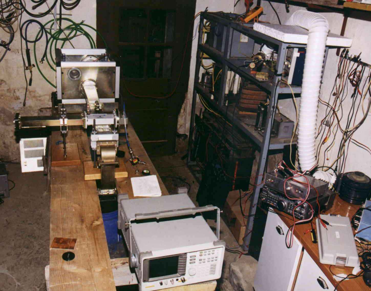
The whole setup looked like this:

The magnetron is in the shiny box in the back. Then comes a transition between two differrent waveguide sizes, and then the section with the tunning screws (they can just barely be seen behind the coupler).
Next comes a waveguide cross-coupler. The left (reflected) coupled port is terminated in the low-power WG load at left, and the right (forward) coupled port goes into a WG/coax transition and then via the blue cable to a 6 dB splitter. The PLL circuit and the spectrum analyzer it feeds aren't yet connected in this photo.
The main power then goes downward to a high-power WG load in the blue water bucket below the table.
The racks on the right contain the (oversized) power supply.