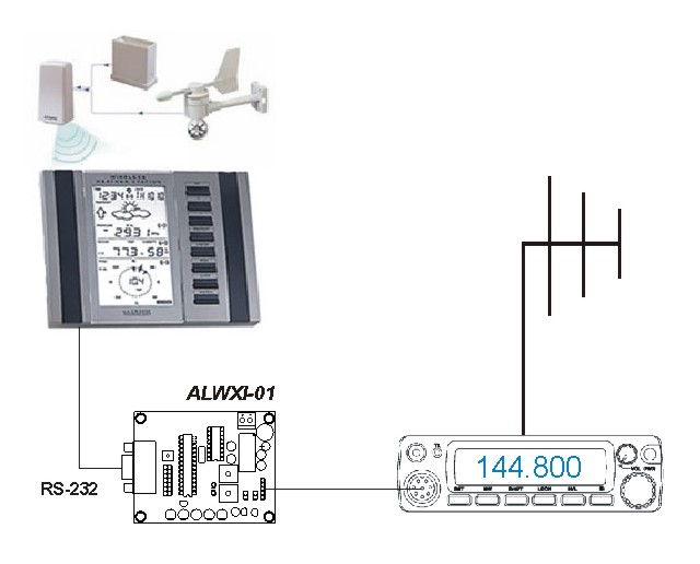
| Amateur weather station to APRS interface ALWXI-01 |
Jumper settings
| JP7 | JP6 | JP5 | JP4 | JP3 | JP2 | JP1 | |
| - | - | - | - | - | - | OFF | TX periode 1 |
| - | - | - | - | - | - | ON | TX periode 2 |
| - | - | - | - | - | OFF | - | Wind speed submitted as "sustain" contains 5 min. average |
| - | - | - | - | - | ON | - | Wind speed submitted as "sustain" contains 5 min. peak (gust) |
| - | - | - | OFF | - | - | - | Lacrosse WS-2300 |
| - | - | - | ON | - | - | - | Oregon scientific WMR-928 |
| - | OFF | - | - | - | - | - | Software correction of the 25,5 m/s wind speed problem disabled (WS-2300 only) |
| - | ON | - | - | - | - | - | Software correction of the 25,5 m/s wind speed problem enabled (WS-2300 only) |
| OFF | - | - | - | - | - | - | Regular operation |
| ON | - | - | - | - | - | - | Enter parameter setting mode at power on |
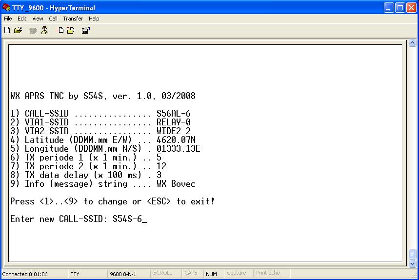
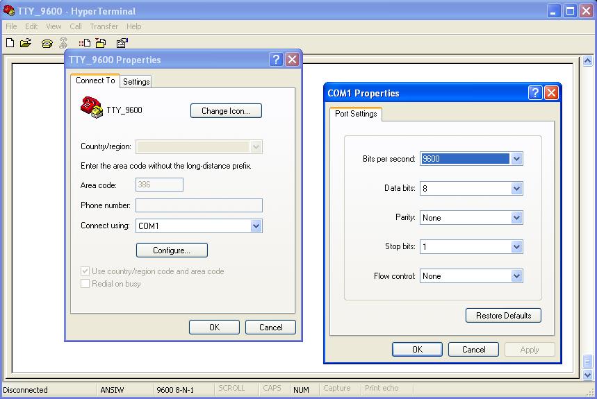
Parameter settings using serial connection
Before putting the WS APRS interface into operation the network parameters should be set. This can be done using a PC connected to the ALWXI-01 through a serial interface. Any terminal emulating SW supporting TTY, VT52 or VT100 mode (HyperTerminal, WTT, etc.) will do the job just fine. Connect the interface to the PC using a three wire cross-connected serial cable (RXD<-->TXD, TXD<-->RXD, GND<-->GND). Run the terminal, configure it to 9,6kbps, 8N1 and no handshaking. Place the jumper JP7 and reset the microcontroller (switch the power off/on). Currently set parameters should appeare on the terminal screen. To adjust the settings just follow the instructions.
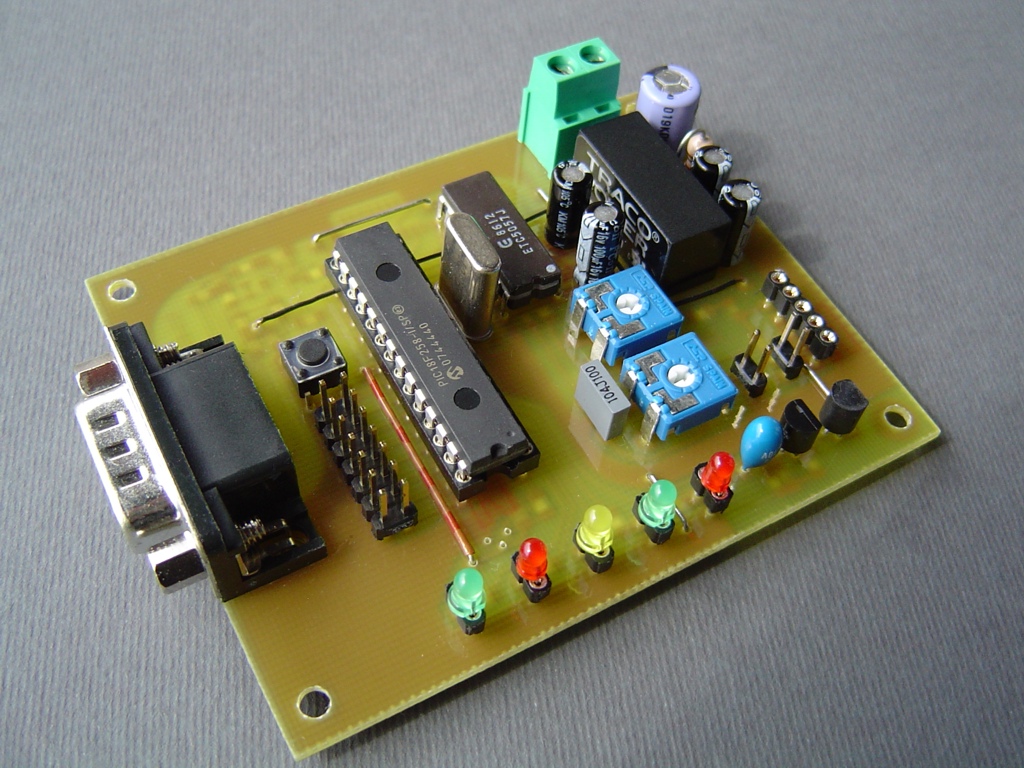
Audio signal level adjustments
ALVXI-01 requires a connection to a 2 m FM transceiver to submit weather data into the amateur packet network (APRS). For proper operation the transmission as well as reception audio signal levels must be set correctly.
TP1 adjusts the receiving signal level. For proper operation the receiver’s audio output (speaker / earphones) must be squelched. Adjust TP1 to the point where LED "REC" reliably turns on while the transceiver receives signals on the APRS channel. When signal appears at the audio input of the ALWXI-01 a busy APRS frequency is being detected and the transmission is being delayed. If the APRS channel doesn't clear out in 45 seconds the ALWXI-01 sends the APRS packet containing weather data "no matter what".
TP2 adjusts the transmitting modulation level. Set TP2 for a proper FM deviation while ALWXI-01 sends an APRS data packet. Signal level at the ALWXI-01 audio output (audio FFSK modulation) can be adjusted in a range of 0 to approx. 0,5 Veff (= 1,5 Vpp). For adjustment purposes a transmission may be triggered manually by pressing TI1. If a transceiver with a sensitive modulation input is being used (for example a microphone input of a typical handy) I suggest to use a resistor divider of at least 10:1 (for example 4,7 kOhm : 470 Ohm or anything close to that value) directly at the microphone input to minimize possible interferences and/or degradation of the modulation quality as well as make level adjustments with TP2 easier.
Last but not least
Some transceivers like older Yaesu handies have PTT input joined with the microphone audio input. To go "on air" those transceivers usually require a grounding of mic. input pin via a resistor (1 kOhm ... 1,5 kOhm) for DC. That's why the R9 is built in. JP10 must be shorted for such operation.
There is an optional IC4 in TO-92 drawn on the assembly plan. This is an optional external reset circuit MC34064-5. It resets the PIC controller whenever the supply voltage drops below 4,5V. PIC already contains some mechanismus to ensure proper CPU start at power up conditions as well as to prevent unexpected CPU behavior at power down like for example unvanted data EEPROM corruption. Therefore if one expects frequent disturbances on the power supply line a use of the external reset IC is higly recommended.
| Back to S56AL page! |