|
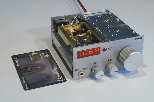
Pocket sized 20m (30m) CW QRP transceiver |
|
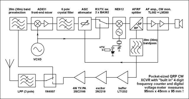
BLOCK DIAGRAM: |
||||||
|
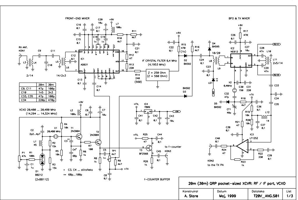
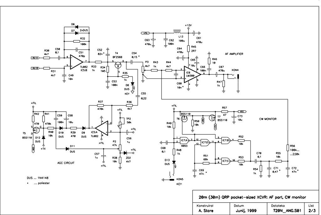
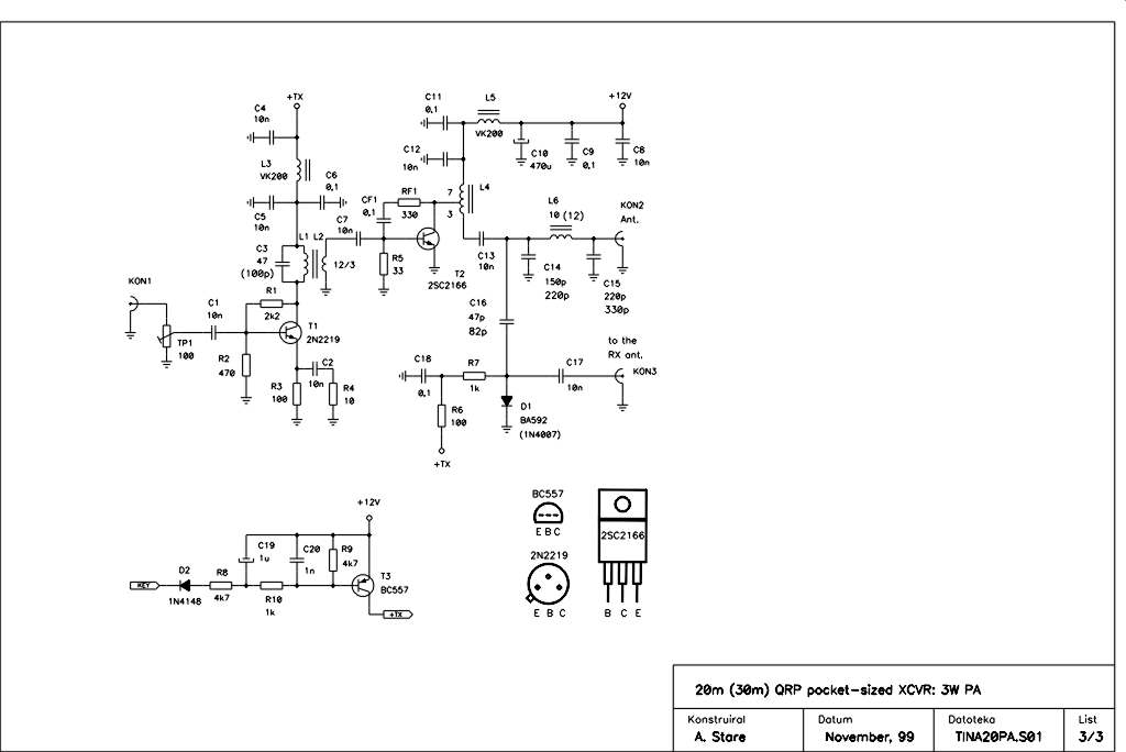
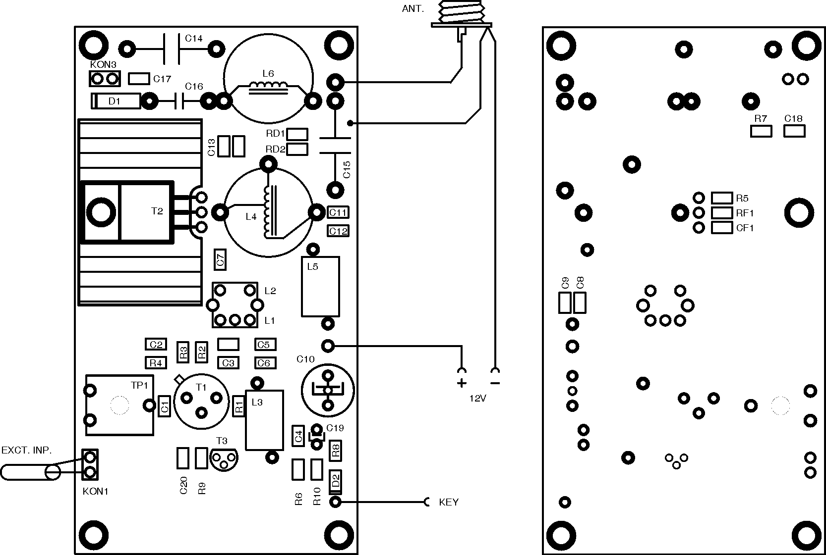
CIRCUIT SCHEMATICS: |
||||||
|
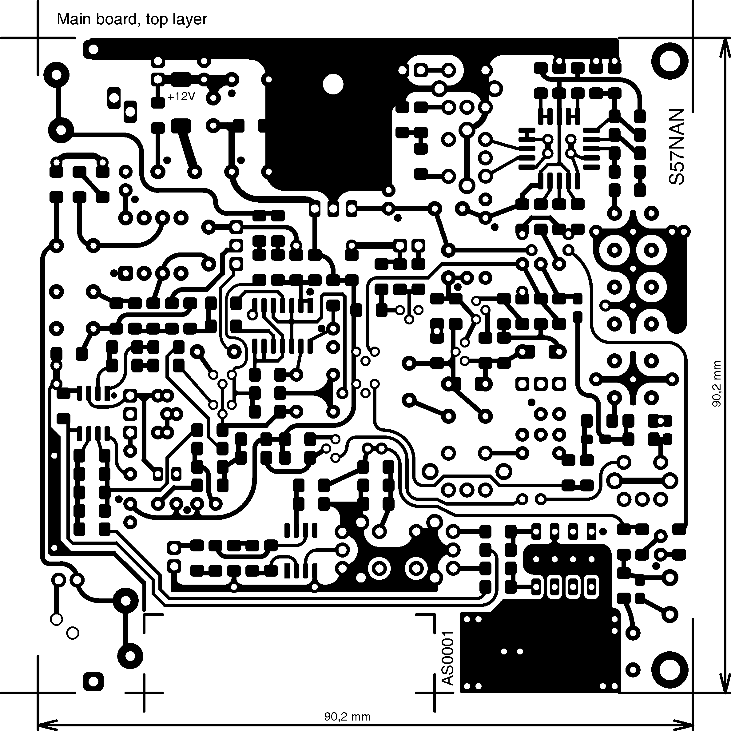
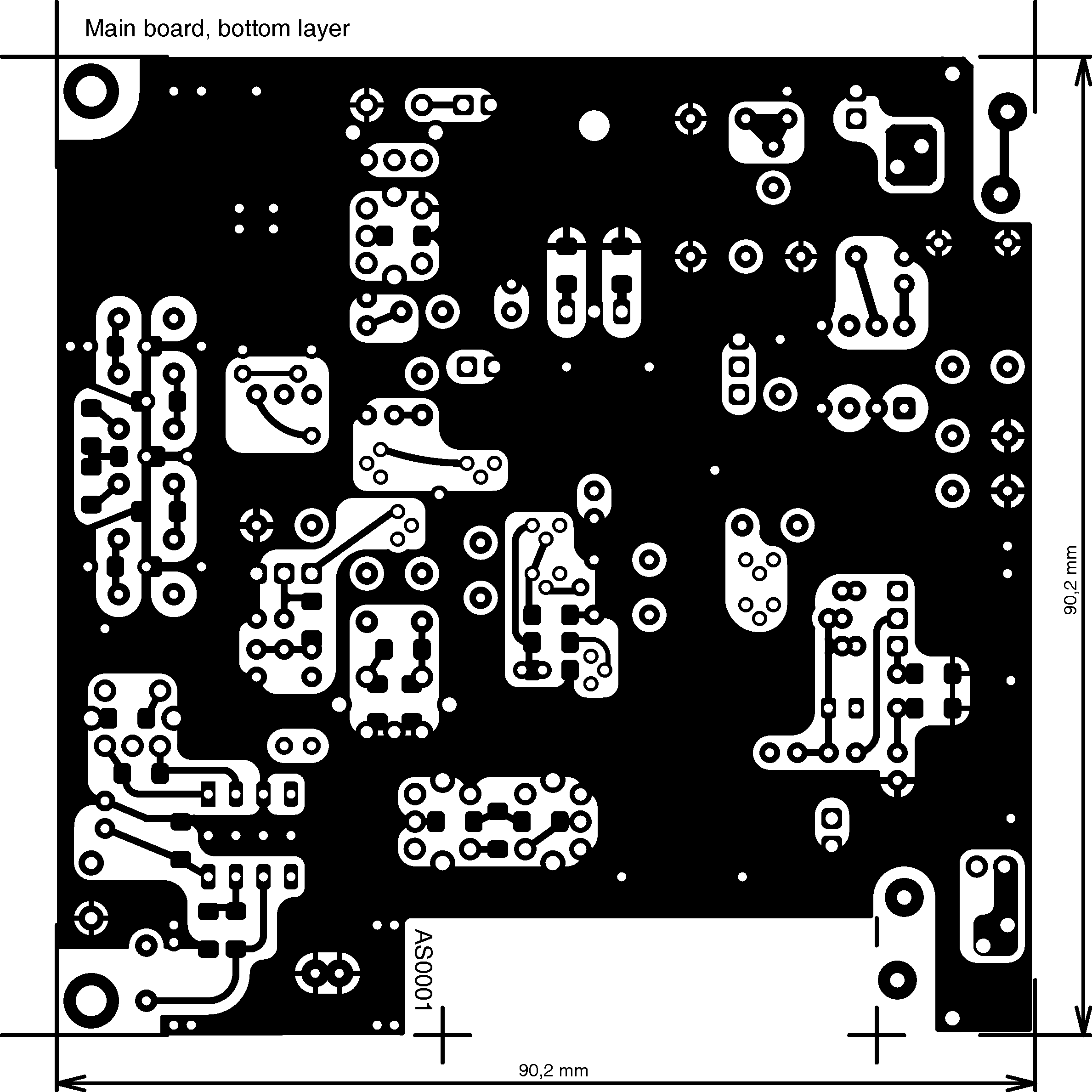
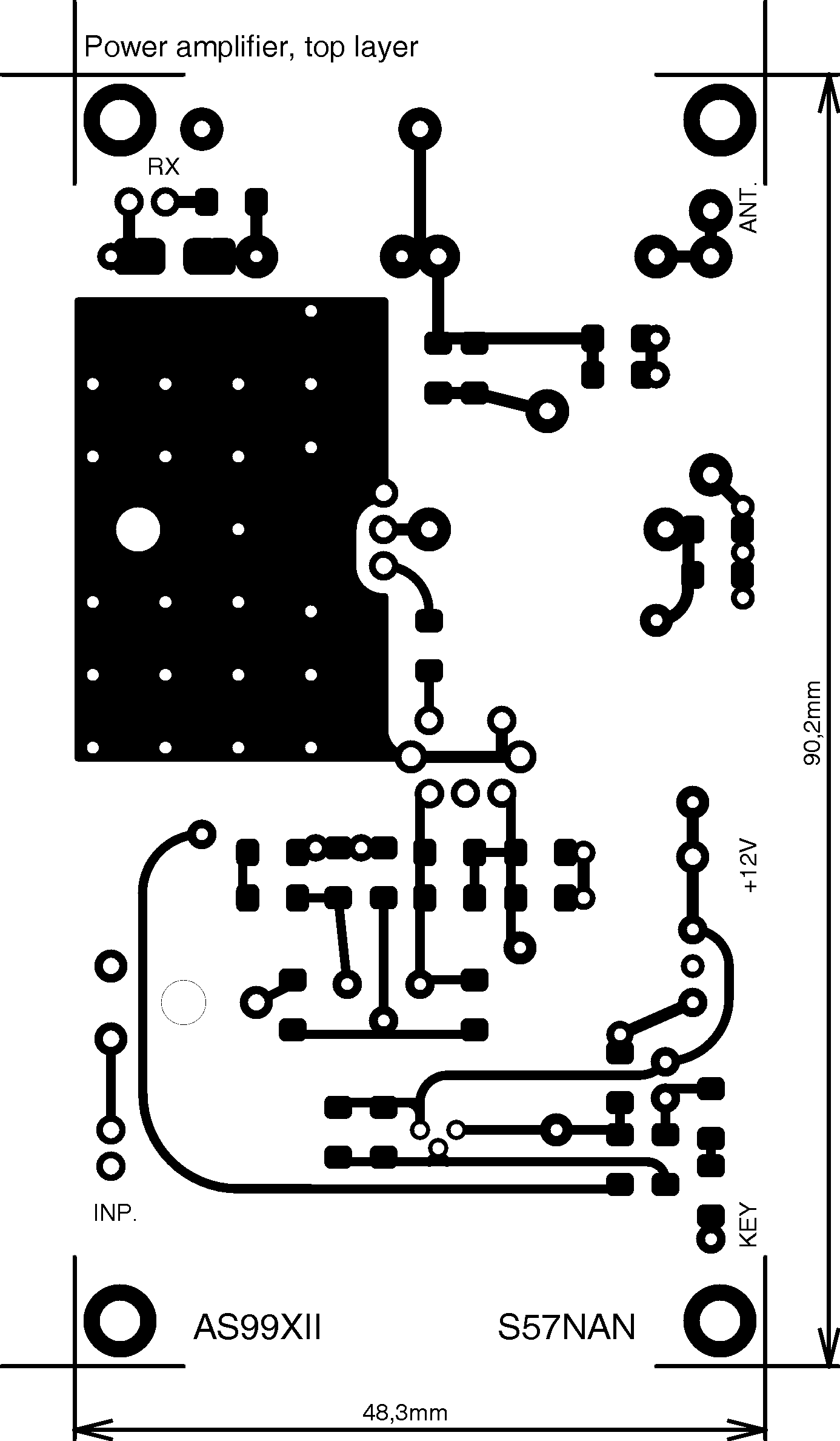
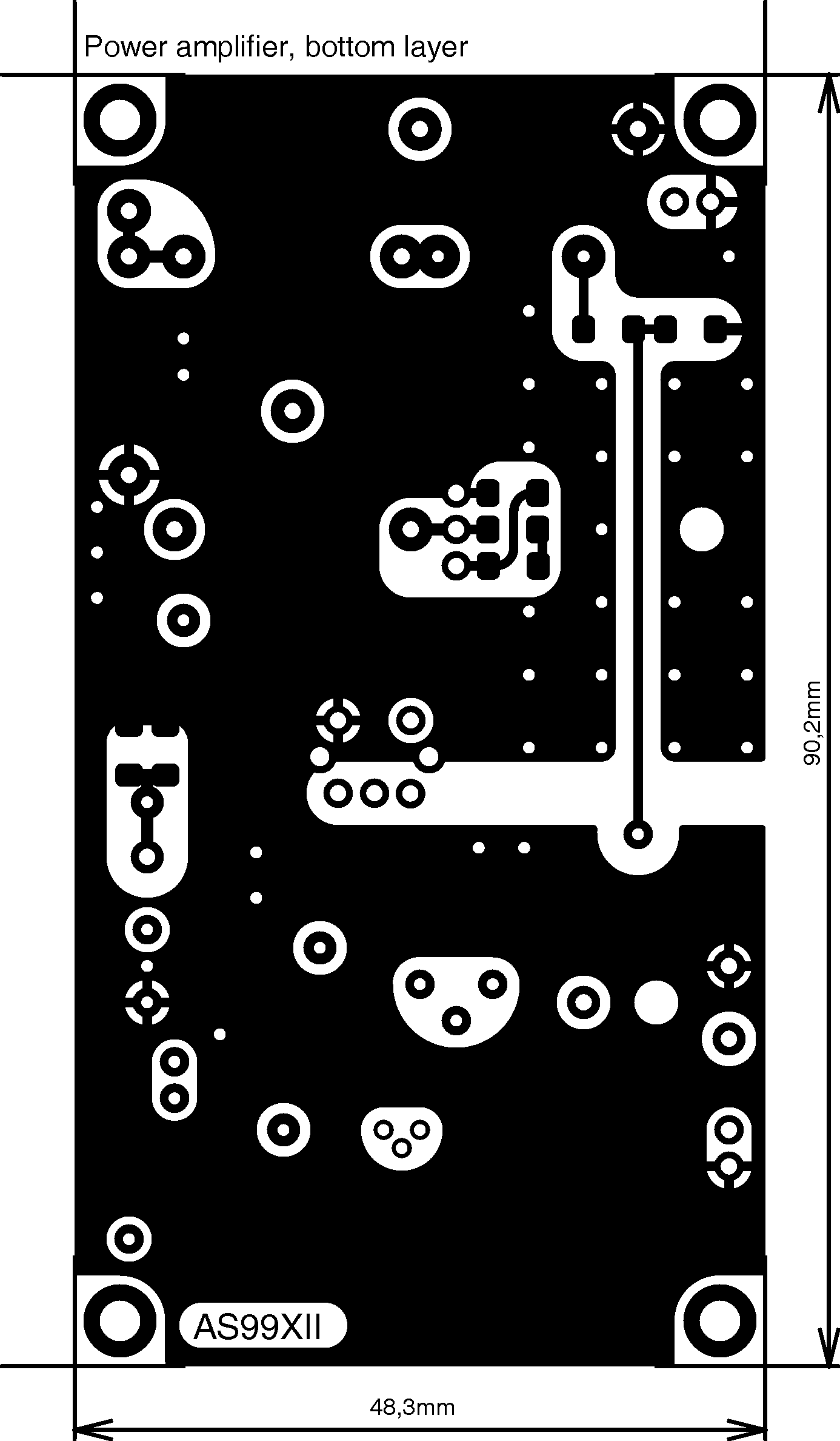
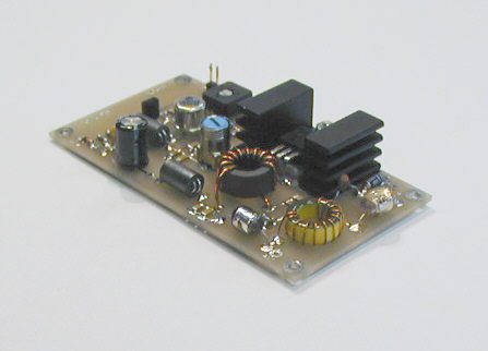
PCB (600dpi gif): |
||||||
|
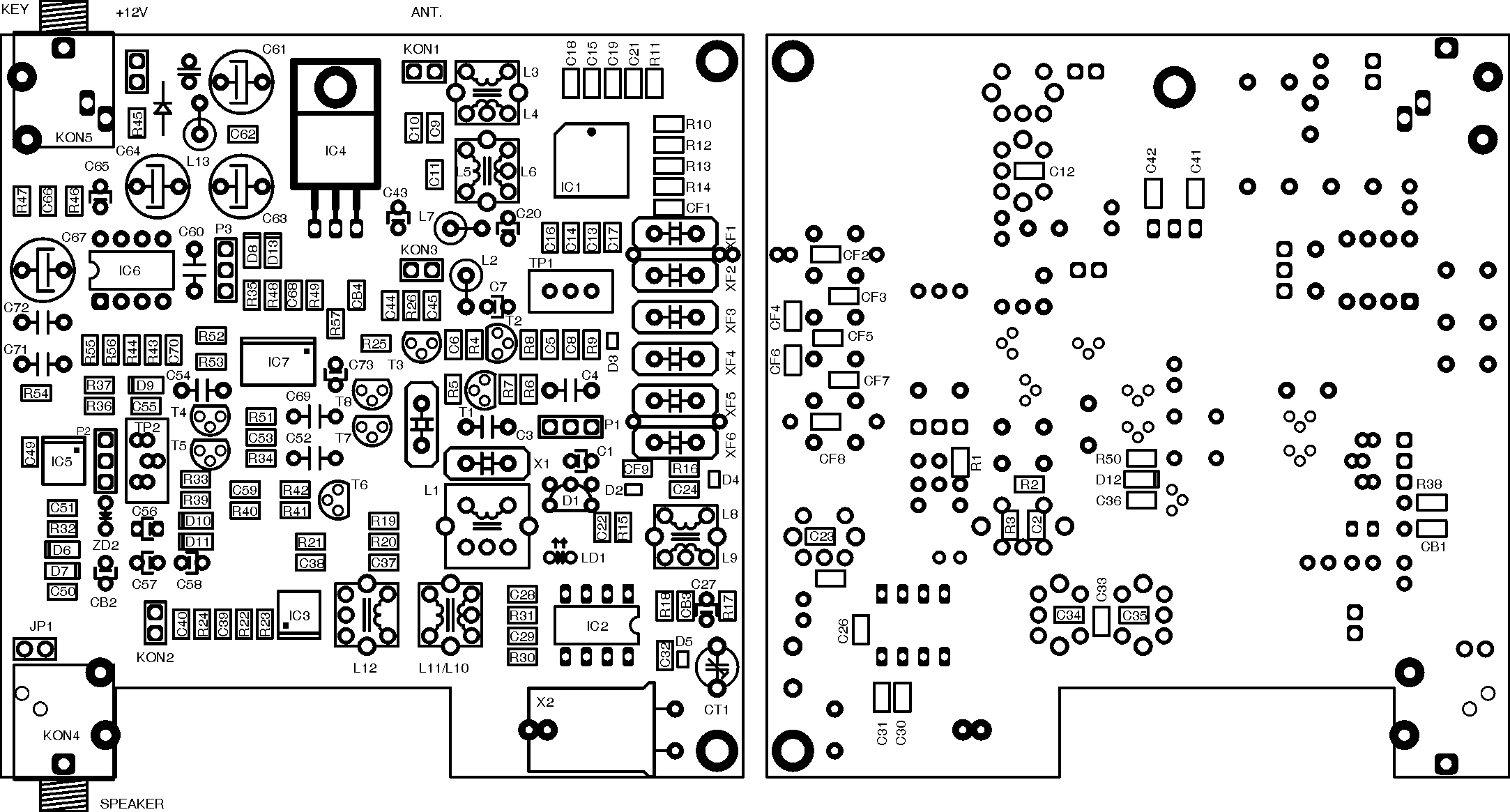
Assembly: |
||||||
|
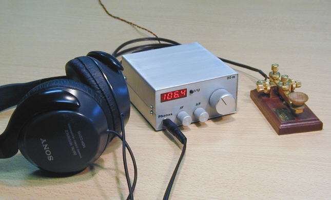
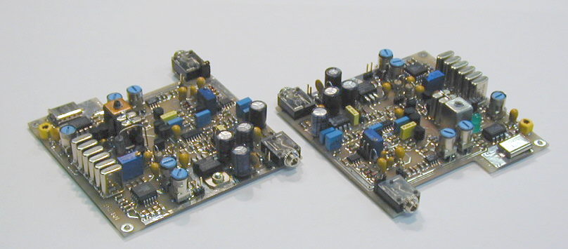
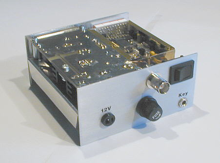
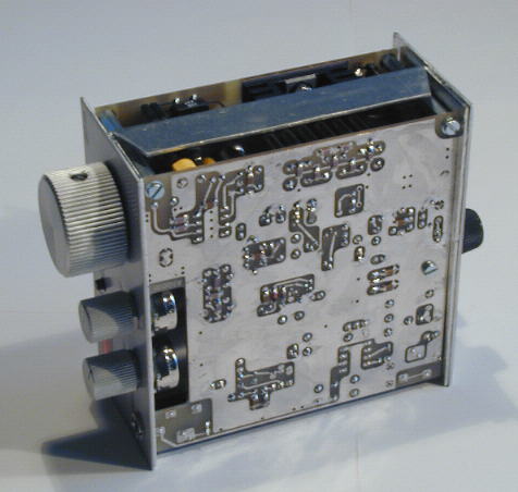
PHOTOS: |
||||||
I started to discover the 30m band by using an adapted version of my
80m single-board CW transceiver. The first impressions were quite encouraging, so I decided to build a portable transceiver for this interesting band. There was no dilemma about the modulation the transceiver has to support, since the SSB is on 30m not allowed. I also decided not just to adapt an earlier design, but to design a completely new transceiver. The goal was to make a gear that would be based on a superhet receiver, would measure less than 10cm x 10cm x 5cm and would include a digital frequency read out. The transceiver should also be "bullet proof" against the strong HF broadcast signals, highly present in the Central European region. The final result was two transceivers built, one for 20m and one for 30m band. I didn't try it yet, but I don't see any serious obstacle to make the same transceiver operating on 17m or 40m band only by wounding appropriate coils and use other IF filter and VCXO quartz frequencies.The first step was to choose the dimensions and type of the housing. I decided to use a "two floor" type of the box. In the upper floor a frequency counter and TX PA are placed and in the "ground floor" there is the rest of the transceiver RF part as well as an AF part including CW monitor, placed on one (main) PCBoard. The "key" and "phones" (speaker) connectors are soldered directly to the main PCB serving also to hold the board in the housing.
After trying different types of FLL, PLL as well as combined PLL + DDS oscillators, I have found out that such a circuit would be very complicated and the signal I would get with such type of oscillator could hardly be so clean as the one I can get from simple VCXO. This was the reason why I have chosen a rather old, but simple and proven solution, although the frequency range the VCXO can cover is strongly limited.
The next task was to choose an appropriate IF frequency. First I tried a 12MHz IF (with 22,118MHz VCXO) as seen in some KITs from USA and GB. I found out that there is a very strong French BC station transmitting on 11,995 MHz, resulting in noise or strongly distorted voice added to the received signal. The frequency is very close to the 20m and 30m bands so it would be impossible to effectively filter it out with the reasonably complex preselection filter. I have had more luck with the combination 4,1943 MHz IF /14,318 VCXO for 30m band and 6,4MHz IF /20,480MHz VCXO for 20m band. With this frequency combination it is easy to cover the 10,100 … 10,128 kHz portion of the 30m and 14,000 … 14,085 kHz portion of the 20m band.
When selecting a mixer, I made some experiments with different available types, to find out quickly, what is the advantage of an SBL-1 passive or AD831 active mixer used in the receiver front-end regarding the quality of the receiver characteristics when compared to the NE602. I decided to use the AD831 because of the simple reason that no additional IF amplifier is needed to get acceptable receiver sensitivity, which is not the case with the SBL-1.
The rest of the circuitry was more or less copied from my already proven earlier designs. I built the transceiver in SMT to get small outline dimensions. All the switching between RX and TX signal paths is done by diodes (BA592, 1N4007) so no relay or other similar electromechanical part is used.
Transceivers with the following IF / VCXO frequency combinations has been also successfully built and tested:
|
Band |
VCXO |
IF |
Frequency coverage |
|
40m |
11,915 MHz … 12,000 MHz |
4,9152 MHz |
7,000 MHz … 7,085 MHz |
|
30m |
14,293 MHz… 14,318 MHz |
4,1943 MHz |
10,100 MHz … 10,125 MHz |
|
30m |
14,100 MHz … 14,165 MHz |
4,000 MHz |
10,100 MHz … 10,165 MHz |
|
20m |
20,000 MHz … 20,480 MHz |
6,400 MHz |
14,000 MHz … 14,080 MHz |
|
17m |
14,068 MHz … 14,165 MHz |
4,000 MHz |
18,068 MHz … 18,165 MHz |
The first version of this transceiver was finished in 1998 and published in official S5 HAM magazine
CQ ZRS (Vol. 2,3,4 /1999). Later I have got some additional ideas how to improve the transceiver, so the version, described on my web pages, is the newer one and dates to the end of 1999. The most important improvement which has been done is that the RX product detector mixer serves also as a transmit mixer, now. The number of implemented mixers has been therefore reduced from 3 to 2.MODIFICATION & IMPROVEMENT HINTS
Recently (Dec. 2004) I've got from Artur SP2QCA the following message about possible noise performance improvement:
Hi Alex, I had a discussion with Marek sp6jqc about replacement of TL082 in order to improove noise in your "Pocket sized 20m (30m) CW QRP transceiver". Marek has successfully built your trx and he found out that OPA2227 has much smaller noise than TL082 while pin-out is the same! Vy 73! Artur sp2qca
* * * * *