 |
SVXlink(SM0SVX) interface board for RPi with fully isolated TRX audio and control signal paths
Back to S56AL main page!
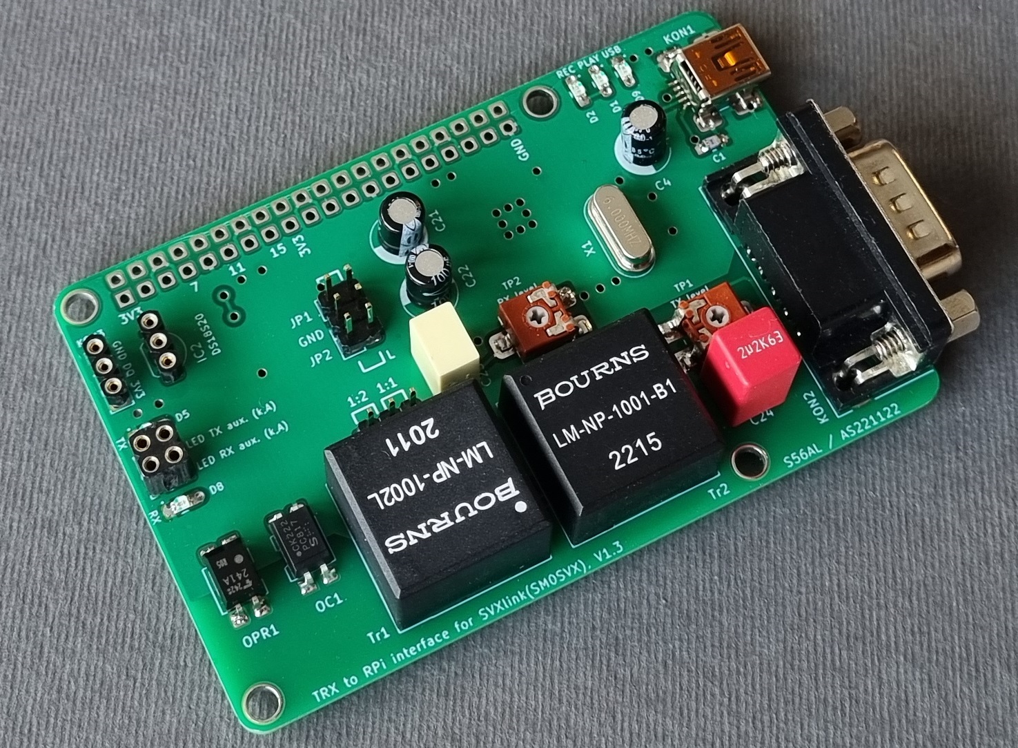
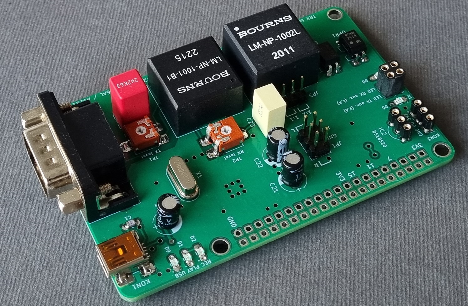
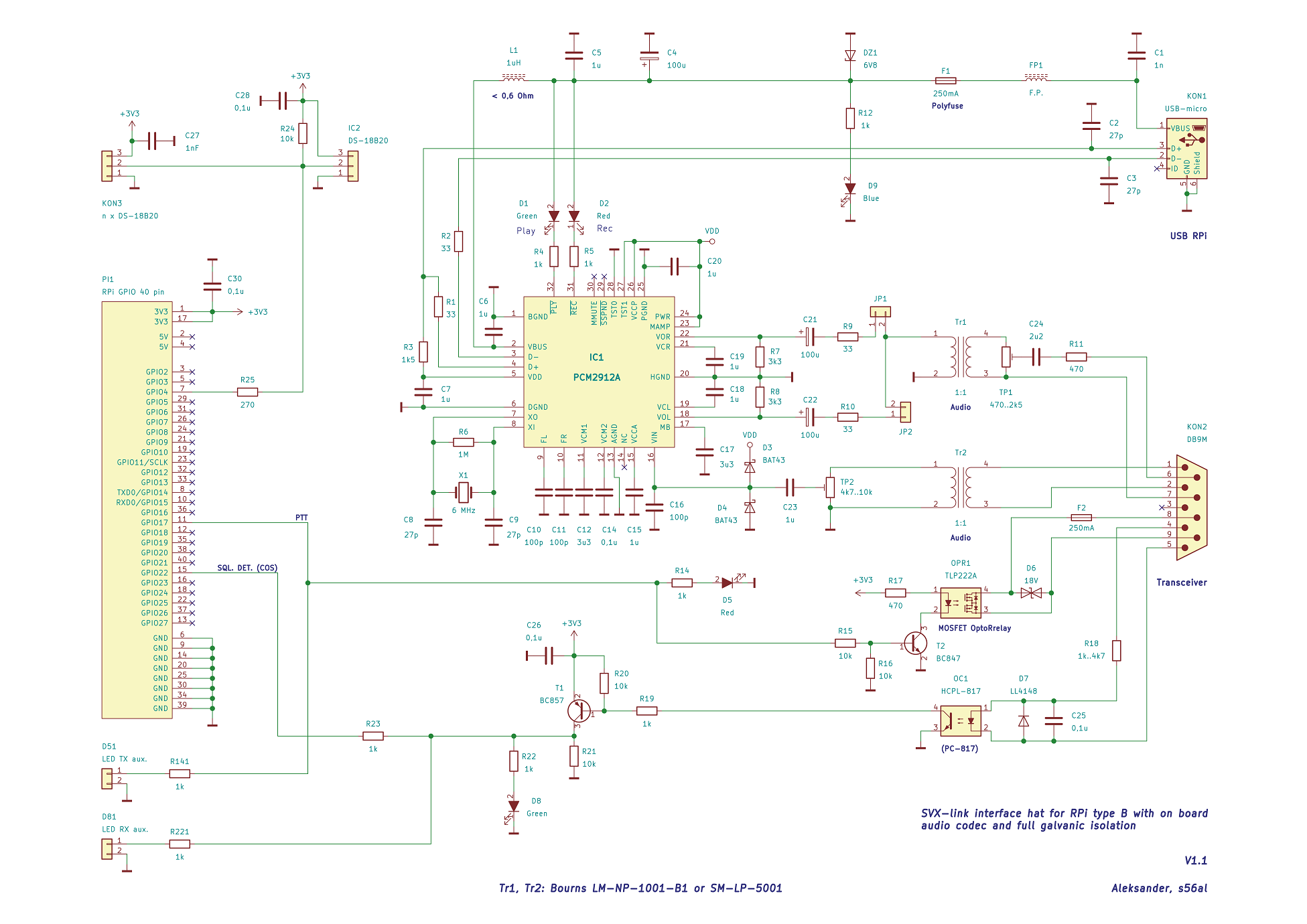
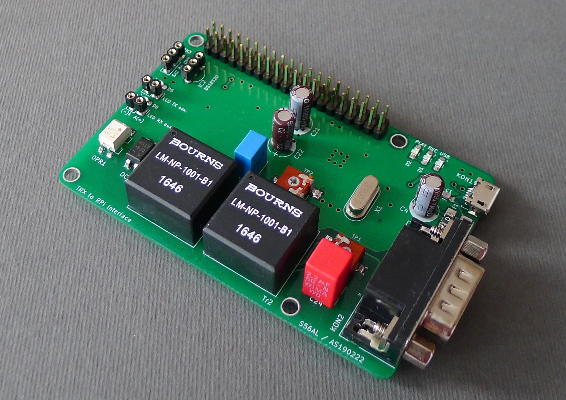
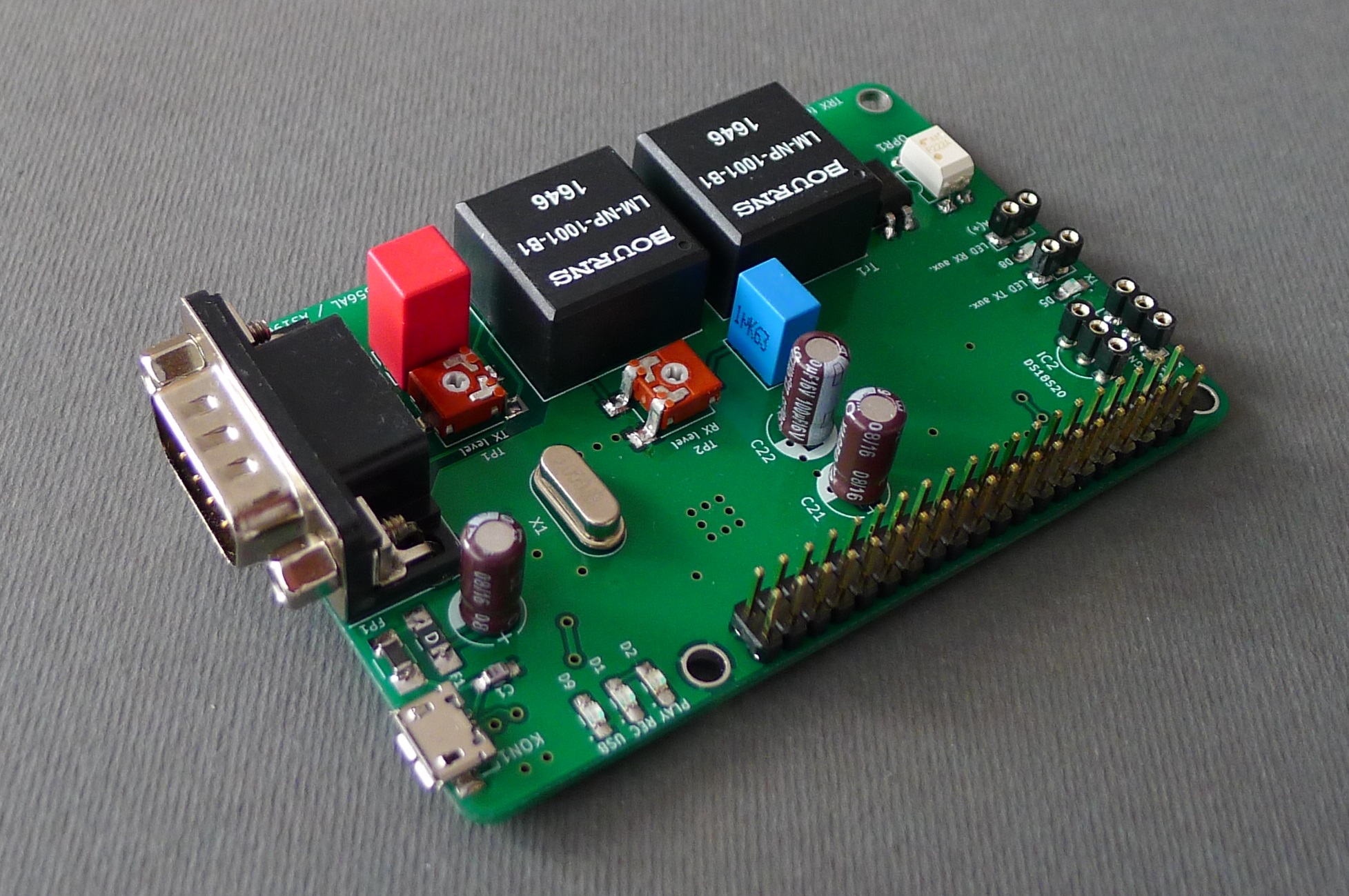
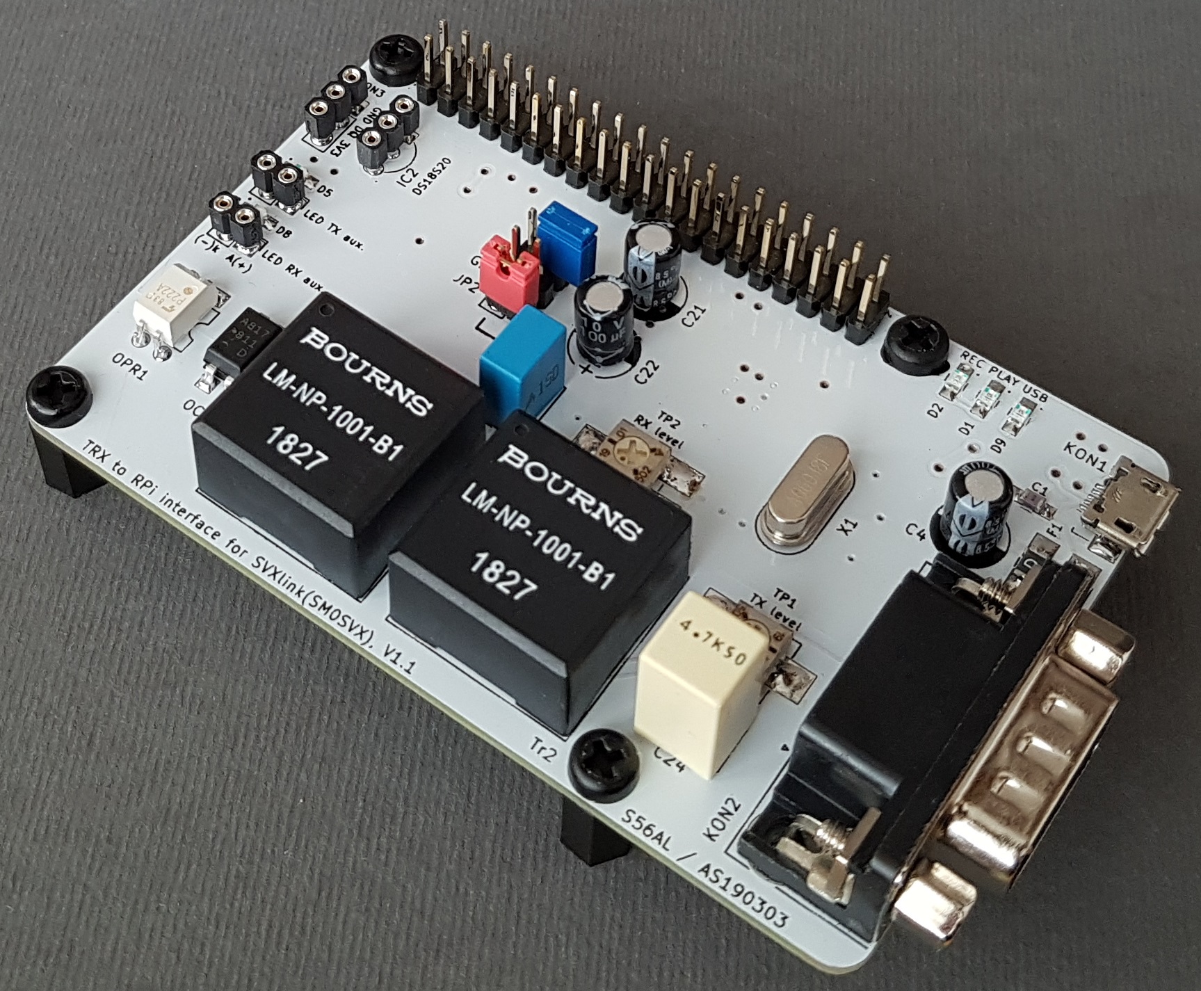
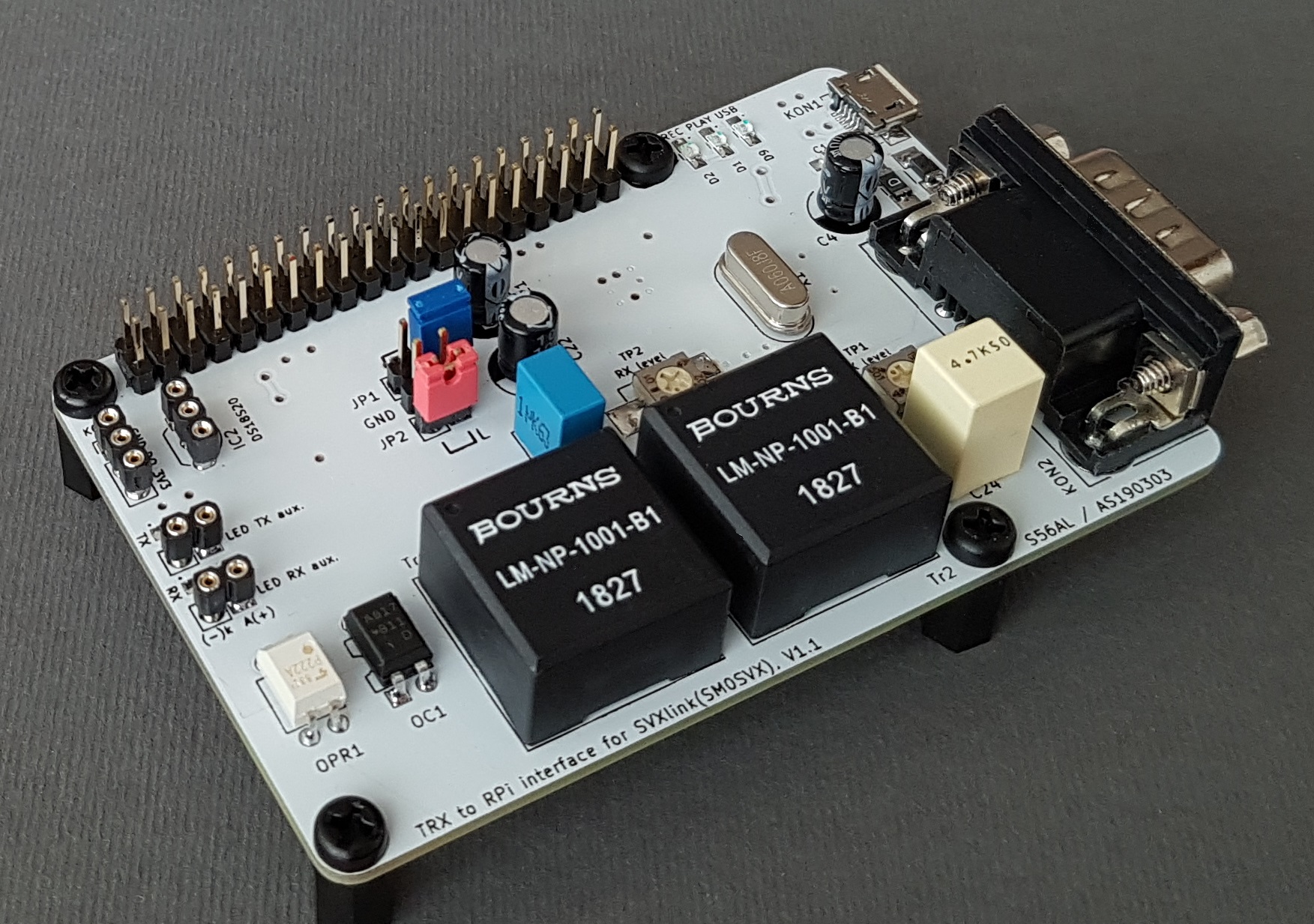
The SVXlink interface board for RPi with fully isolated TRX audio and control signal paths integrates an onboard USB sound chip, two audio transformers, optocoupler for squelch detect as well as an optorelay for strong PTT to TRX isolated audio and control signals!
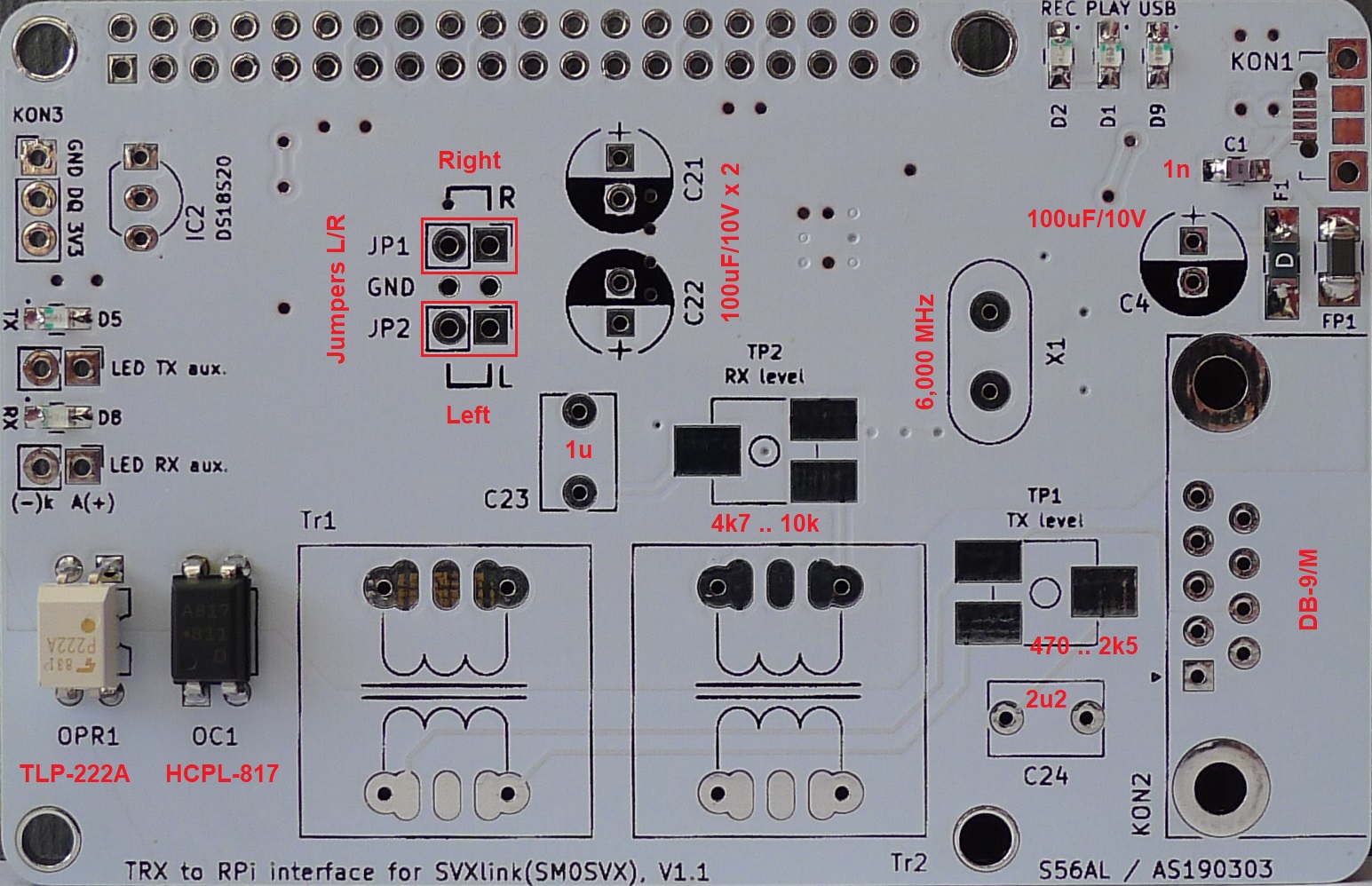
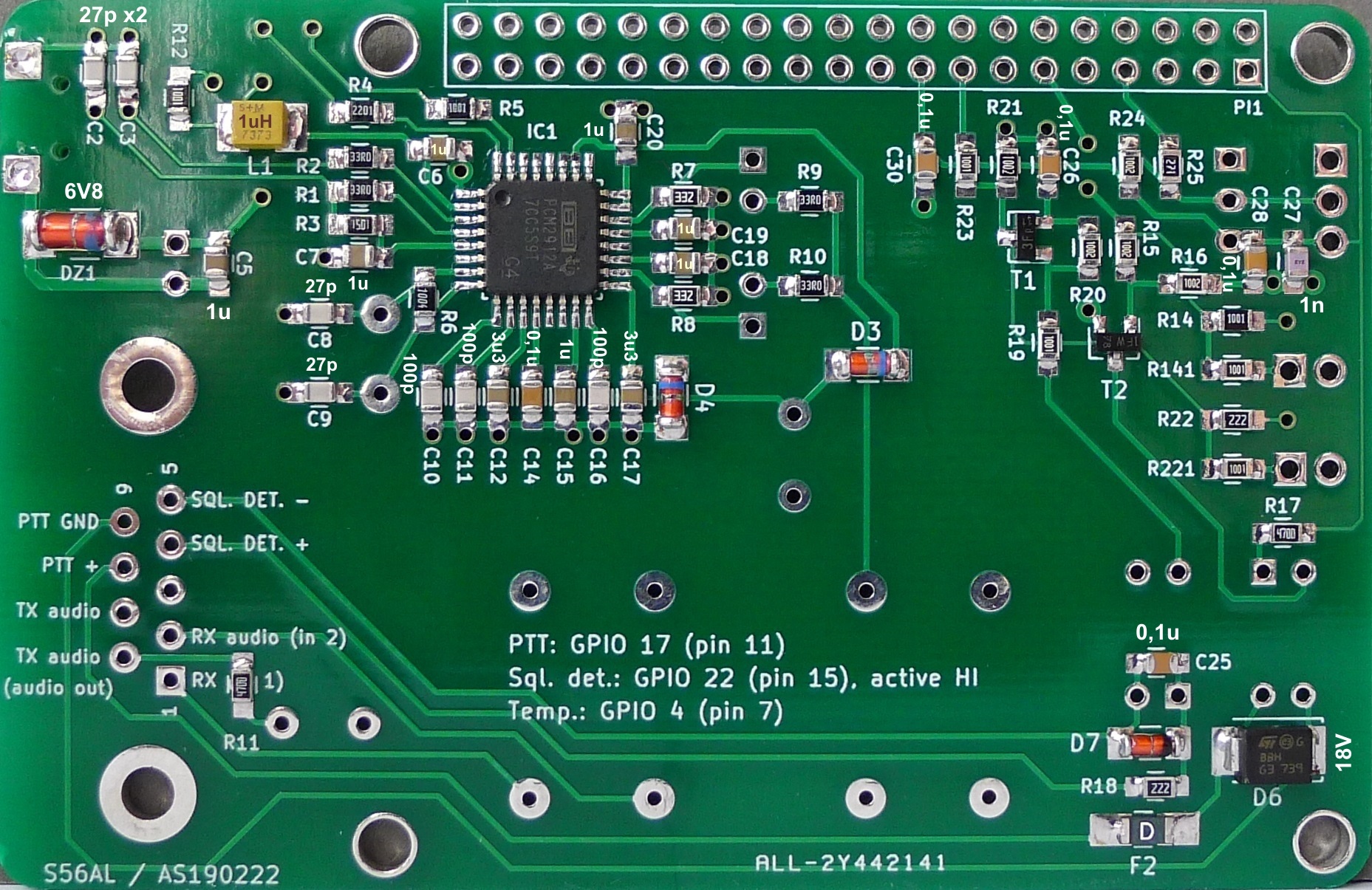
Implemented SMD components (R, L, C) of size SMD "0805" or bigger for easy and comfortable handsoldering should provide a friendly assembly of the board to a homebuilder who only has access to an average equiped amateur workshop. Furthermore the pads of SMD components are also dimensioned in somehow excessive size to allow more comfortable hand soldering even by a not so experienced builder.
|
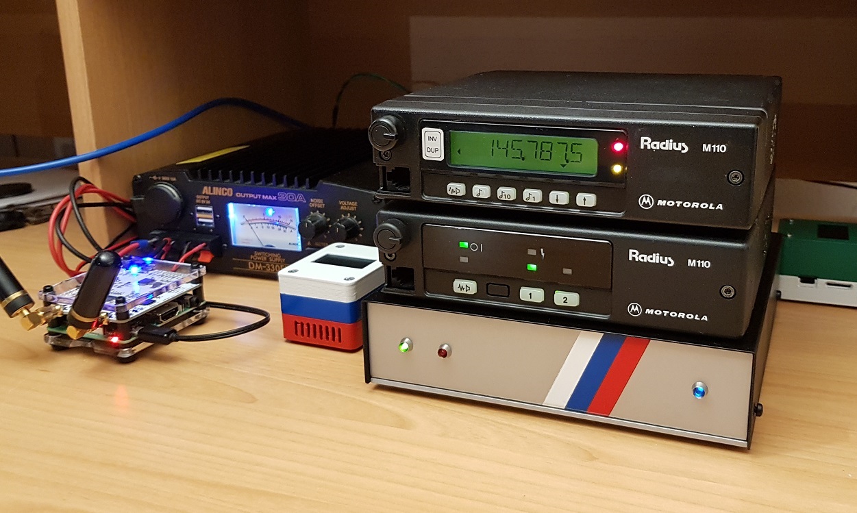
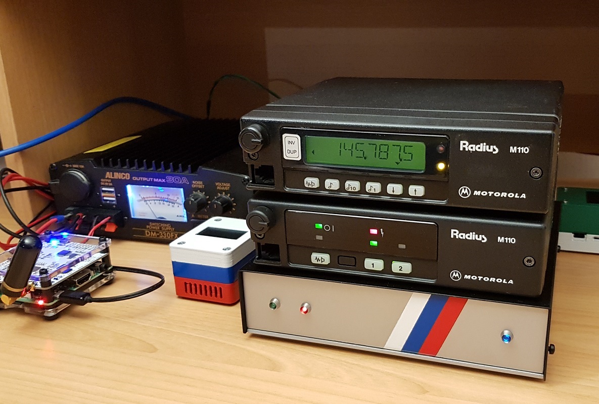
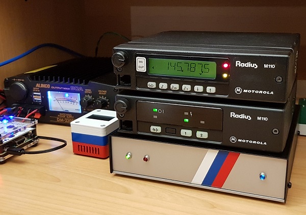
Our local 2m FM repeater S55VTO (former S55VTO) located @ JN66RI / 2202 m ASL and installed back in 1984, has been connected to the Echolink network for more than 10 years. The Echolink GW equipment, based on a Mini-ITX PC computer and a
homebrew SVXlink Interface board with integrated DTMF decoder
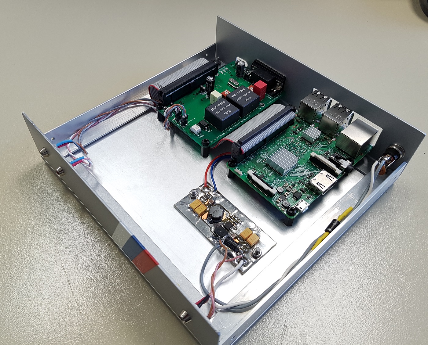
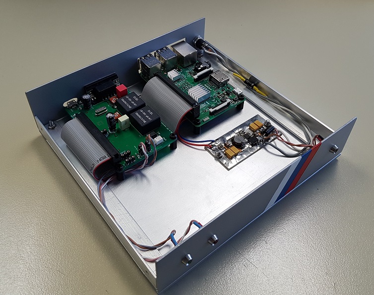
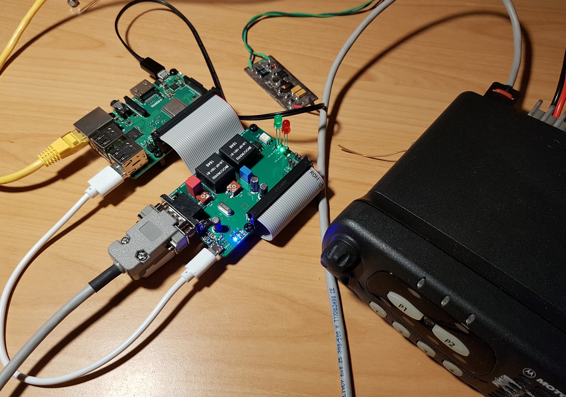
has been faithfully serving the purpose for the last 8 years. However, after the Mini-ITX computer recently "died", I have decided to go with a Raspberry Pi (RPi) instead of a traditional PC this time.
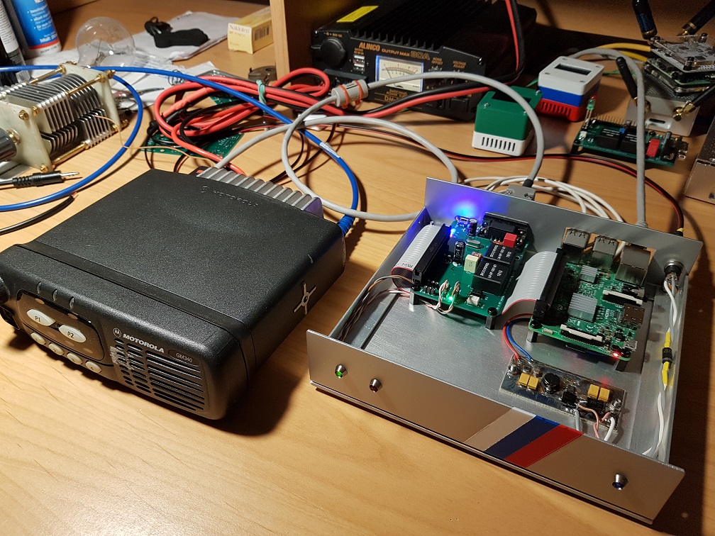
To connect the existing radio equipment to a RPi a new interface board had to be designed and built. Based on the 10 years of experiances the new board still offers a fully isolated TRX to RPi audio and control signal paths. Since the RPi itself has no on-board audio input, an USB sound chip has been added to the new interface board. The software DTMF decoder, built into the SVXlink SW package, seems to improve significantly over the last 10 years, therefore there was no longer need to keep it on the new interface board as well.
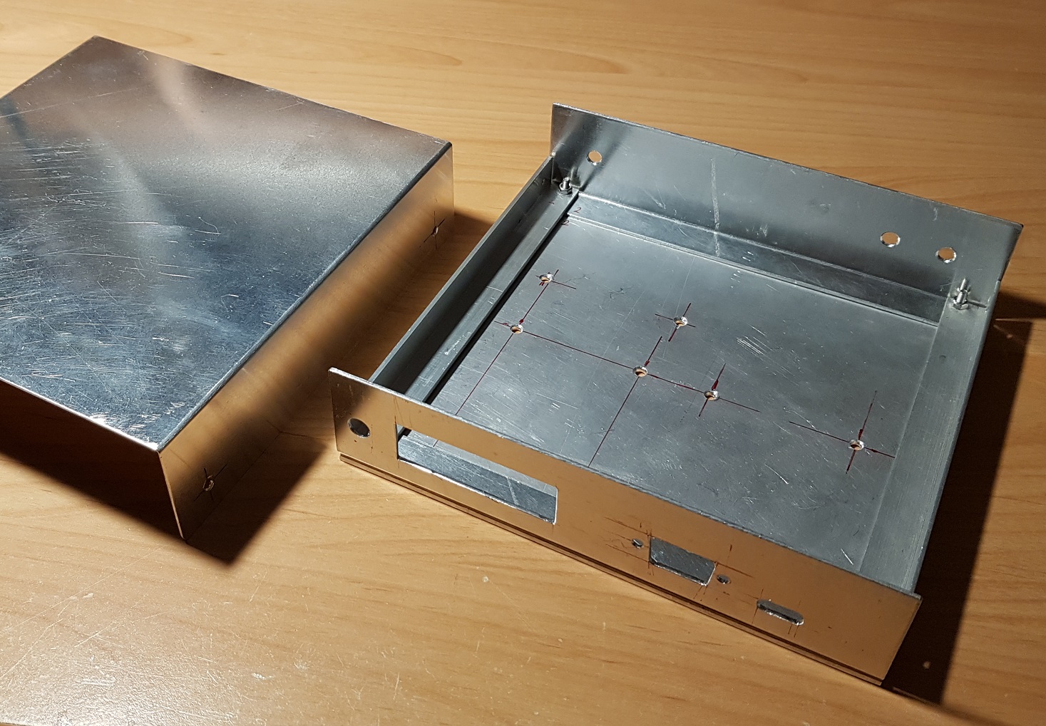
Revision V1.3 (November, 2022)
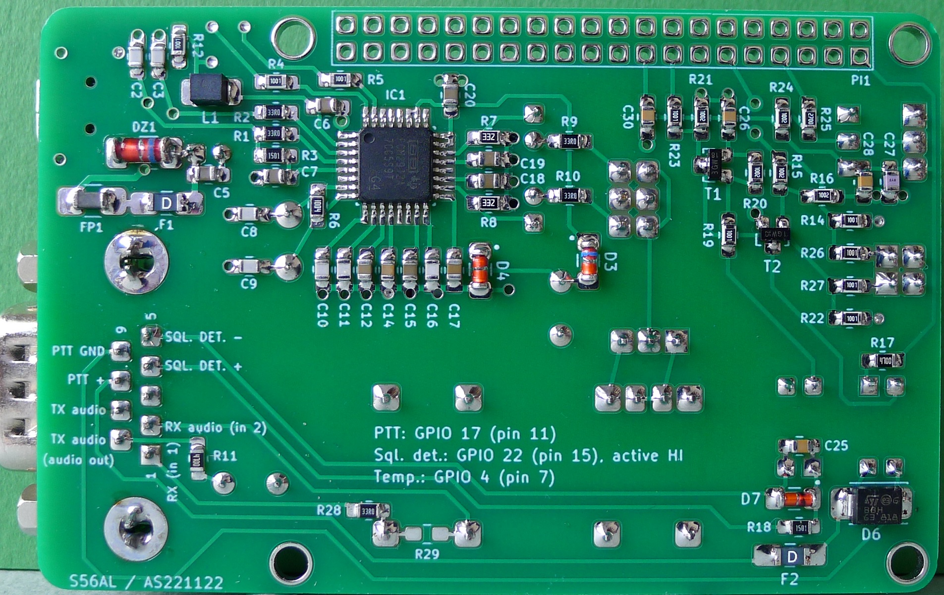
The "Micro-USB" connector used in previous versions has been replaced by a more durable and mechanically stable "Mini-USB" type.
Two resistors (R28 and R29) have been added to the board so that an input audio attenuator can be configured for easier and more accurate audio input level adjustment (TP2) in the case of high input levels.
A center-tapped transformer can be installed at the audio output, allowing for a flexible (configurable) transformation ratio. The USB sound chip PCM-2912 offers a decent amount of "MiliWatts" at its output. However, the chip is designed to drive a set of low-impedance earphones (typically 20 to 30 ohms), consequently the output voltage may not be sufficient to drive a high-impedance modulation input, especially in the case of some older professional repeater systems. In such a case a 1:2 voltage transformation may be convenient.
Versions 1.0 and 1.1 (Februay / March, 2019)