|
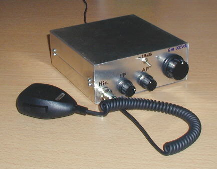
6m SSB & CW QRP transceiver |
NEW Latest comments… NEW |
|
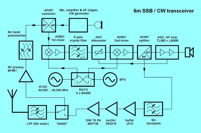
BLOCK DIAGRAM: |
||||
|
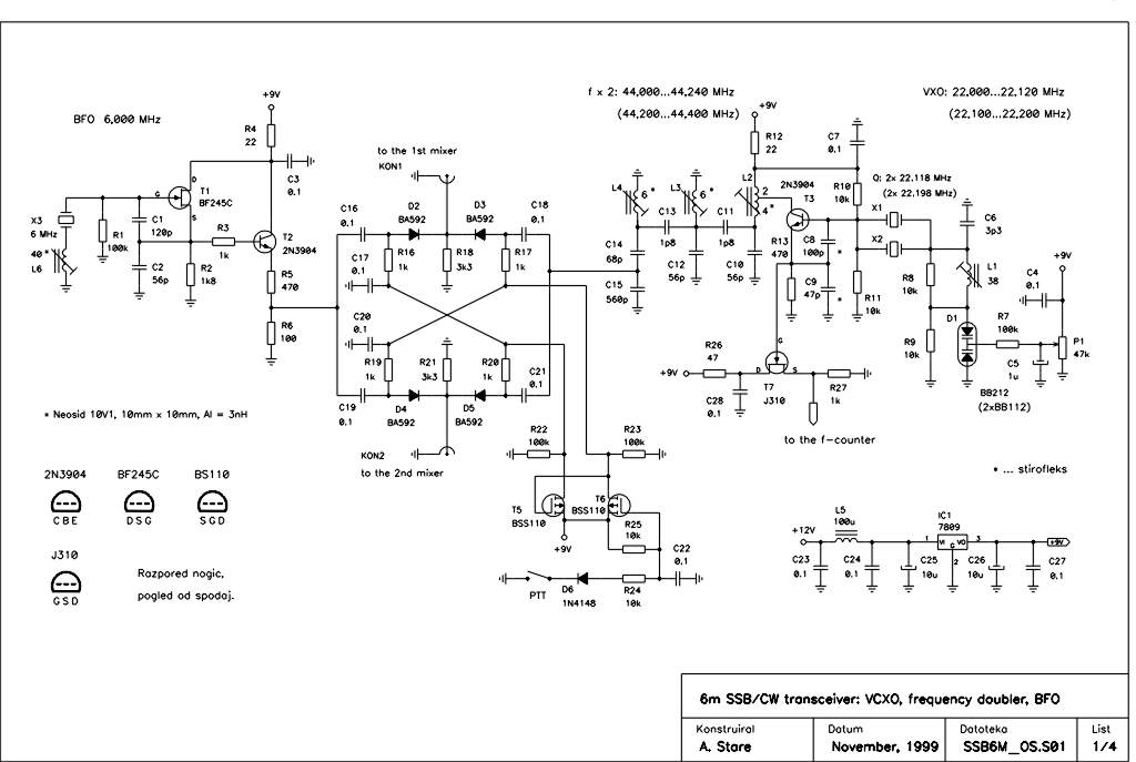
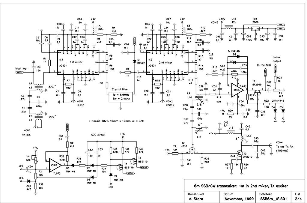
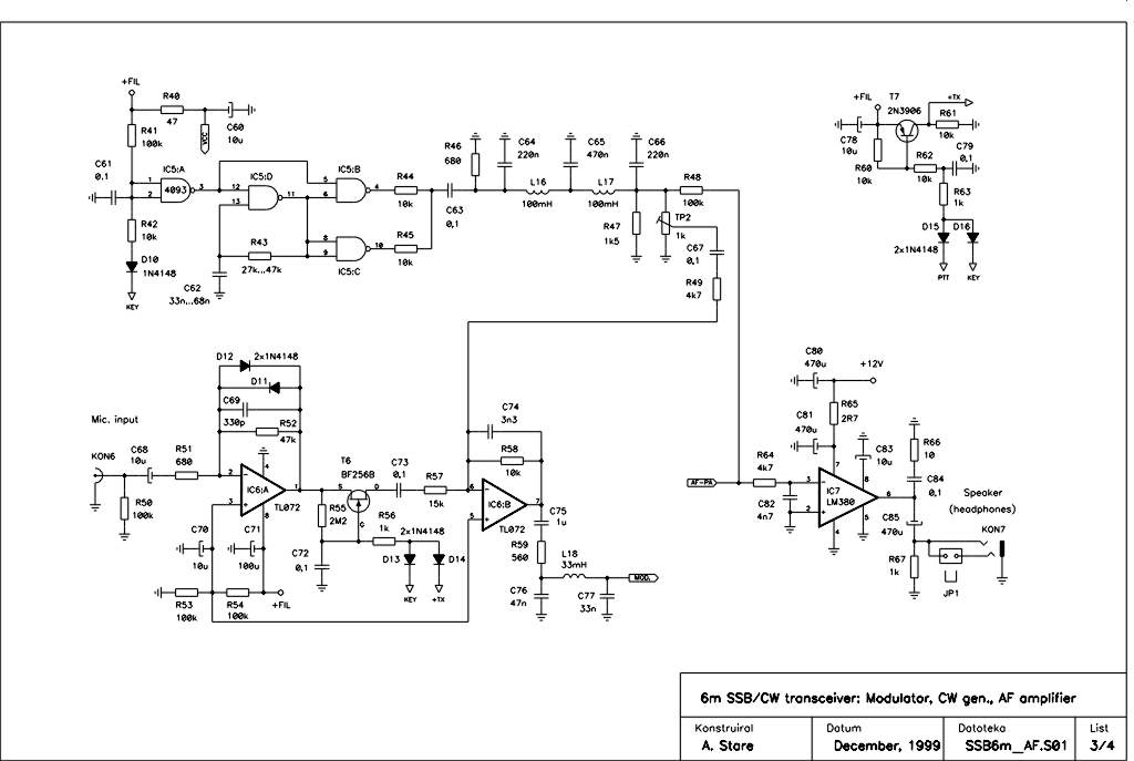
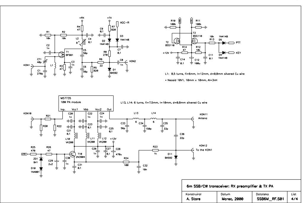
CIRCUIT SCHEMATICS: |
||||
|
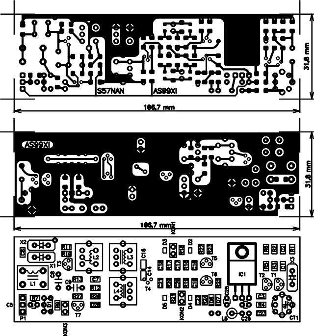
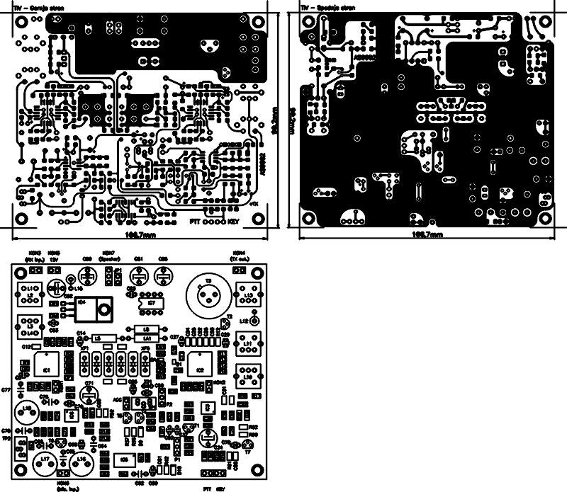
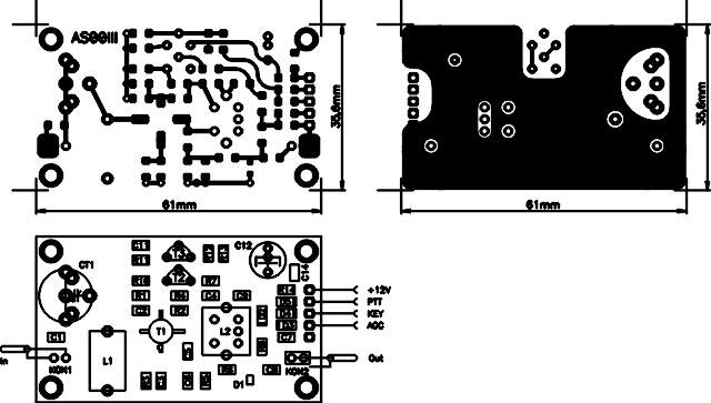
PCB LAYOUT: |
||||
|
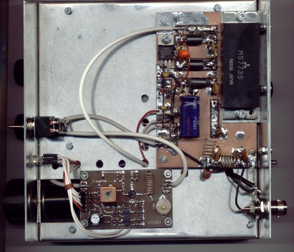
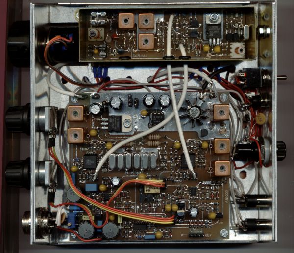
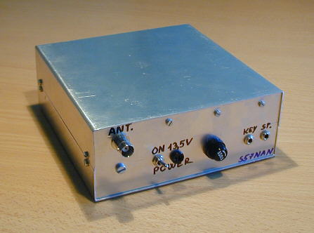
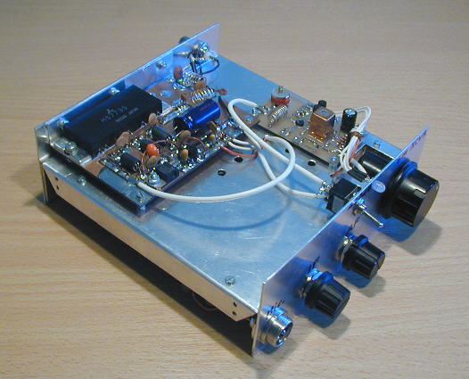
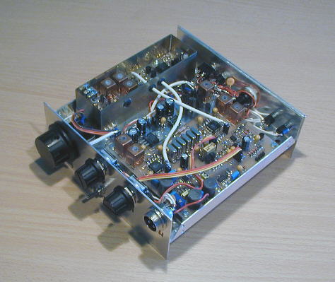
PHOTOS: |
||||
|
|
||||
The concept of the 6m SSB & CW transceiver is similar to the
80m SSB & CW transceiver, described on this web site with some minor changes in AGC and audio PA. An additional RF preamplifier, which is not needed on 80m, has been added to get enough receiving sensitivity. The VFO is built as VCXO with frequency doubler, now.Although the basic SSB module is very similar to that of 80m SSB transceiver, I've designed completely new PCB to maximise the usage of SMT components. The transceiver "base" board includes all IF and AF circuits, both mixers, preselection and bandpass filters, as well as 100mW TX driver. This is in fact a complete transceiver. Only the VFO and BFO have to be added to get a 100mW (QRPP
J) HF SSB/CW transceiver. Both oscillators including a diode-switching matrix are placed on a separate board.RX preamplifier is built around a BF981 MOSFET placed on a separate PCB. The preamplifier has some 20dB gain.
For the TX PA I have chosen a rather easy solution - 10W Mitsubishi PA hybrid module. I've built the TX PA in an "ugly" way on a "hand-made" double-sided PCB. The bottom layer serves as ground. All components are placed on the top side of the board.
Experiences show, that the frequency stability of the VCXO highly depends on the temperature stability of the capacitors C8, C9, temperature coefficient of the L1 as well as covered frequency range - wider the frequency range covered, poorer the stability. I've used styroflex (polystyrene) type of capacitors of larger size at the place of C8 and C9.
The generated harmonics and subharmonics at the VCXO output may result in the reception of the unwanted RF signals (outside the 6m HAM band). There are more possibilities for choosing the VCXO and IF frequency using standard available quartz crystal:
|
|
XTAL |
Multip. |
VCXO out /MHz |
IF /MHz |
Covered freq. range /MHz |
|
1. |
22,118 |
x 2 |
44,000 … 44,250 |
6,000 |
50,000 … 50,250 |
|
2. |
22,118 |
x 2 |
43,865 … 44,250 |
6,144 |
50,000 … 50,395 |
|
3. |
22,198 |
x 2 |
44,400 … 44,000 |
6,000 |
50,000 … 50,400 |
|
4. |
22,118 |
x 3 |
66,000 … 66,375 |
16,000 |
50,000 … 50,375 |
|
5. |
22,118 |
x 3 |
66,000 … 66,375 |
6,000 |
72,000 … 72,375 |
I've used the combination under 1., which performs quite well, only that the transceiver would receive also the 22,118 + 6 MHz, which is exactly in 10m HAM band, if such (very!) strong signal is present. This is due to the fact that the basic frequency of the VCXO at 22,xxx MHz can not be eliminated completely by the 44MHz band-pass filter. The combination under 4 is "immune" to the 10m band signals because of the different IF frequency.
Please observe that there are additional pads on the PCB prepared for a source-follower with J310 at the output of the VCXO LC band-pass filter. It may be used if the VCXO output power is not strong enough to drive the mixer. In my case this was not necessary. Adding source follower introduces further harmonics in the VCXO output spectrum. By my opinion this is not of bigger importance, since the VCXO signal is transformed from sine into the rectangular waveform by an amplifier/limiter at the AD831 L.O input.
Of course, other combinations of the VCXO / IF frequencies are also possible. A little exercise with calculator is worth of the spent time, if some custom made quartz is available. One only has to be sure that the crystal-pair will pull over the required frequency range. For further questions please contact me via e-mail.