| A simple FM repeater controller and morse coded ID message generator
Back to S56AL main page!
|
|
|
|
 |
 |
 |
| PIC16F628A assembly source code (15 kB - zip) | PCB layout - Gerber files (170 kB - zip) |
Please note: For a successful completion of this project, it is besides a good understanding of the analog repeater systems operation, also necessary to master at least the basics of the PIC16F microcontroller family assembly code compiling and programming, audio signal processing, SMD component soldering as well as to own necessary tools to get the job done.
Sometime about 20 years ago a fellow HAM suggested building A simple morse coded ID message generator to be used with a local FM repeater. After a successful design and assembly of the first prototype it later turned out the same hardware can also serve as a simple FM RPT controller only by enhancing the firmware with a more advanced set of the controller functionality . At the end of the day only one repeater "in the field" has been actually equipped with the basic morse code ID message generator while more than 10 older FM repeaters has been upgraded to the enhanced software version, providing basic RPT controller functionality rather than a bare ID message generator only. Some 6 or 7 of those have still remained on duty until present.
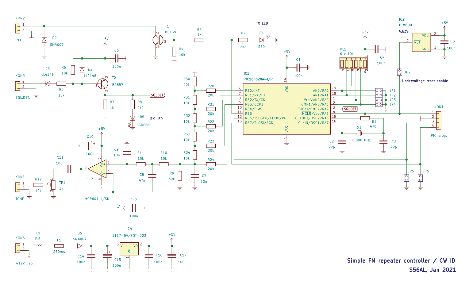
Now, if you check the circuit above, you will notice that the basic schematics of the original design included a simple hardware based "PTT hold" time limiter. Many of the repeaters, sitting on the top of the hills are hard to reach, especially in the winter time. A microprocessor program execution can run into many sorts of troubles anytime (in the worst case crashing while PTT control remains pulled down) and making such a circuit like a sensible solution at the time. However, later a lot of experiences has been gained by a practical installations of RPT controllers, not just the simple ones as mentioned above, but also much more complex systems, containing of up to 5 8-bit PIC16 and / or PIC18F series of devices working together in a well intertwined system. It turned out that if properly designed and integrated into the circuitry the PIC16F and 18F series of devices are highly reliable building blocks. During all these years there was no case reported (or noted) that such a device would "crash" or otherwise cause any sort of malfunction.
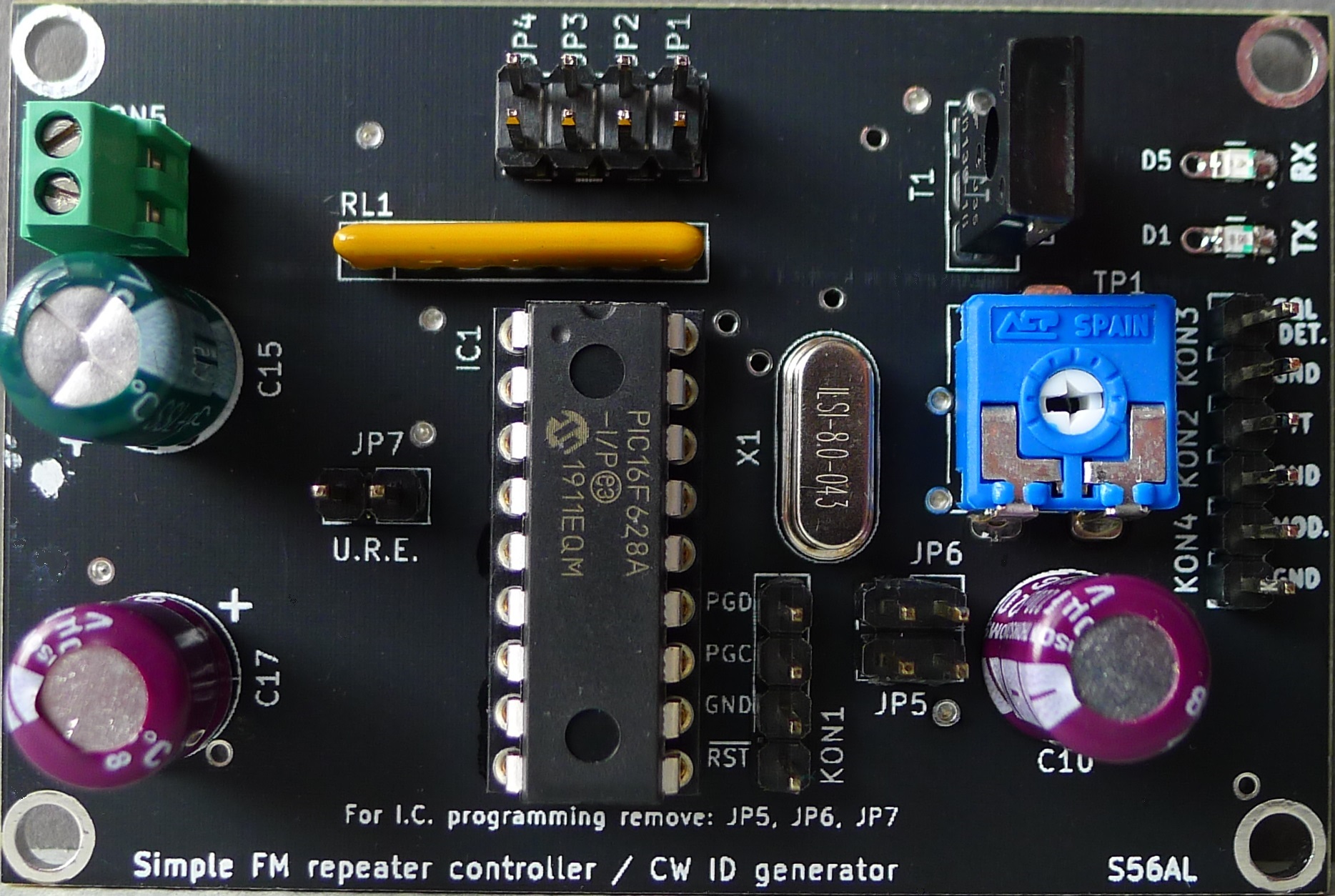
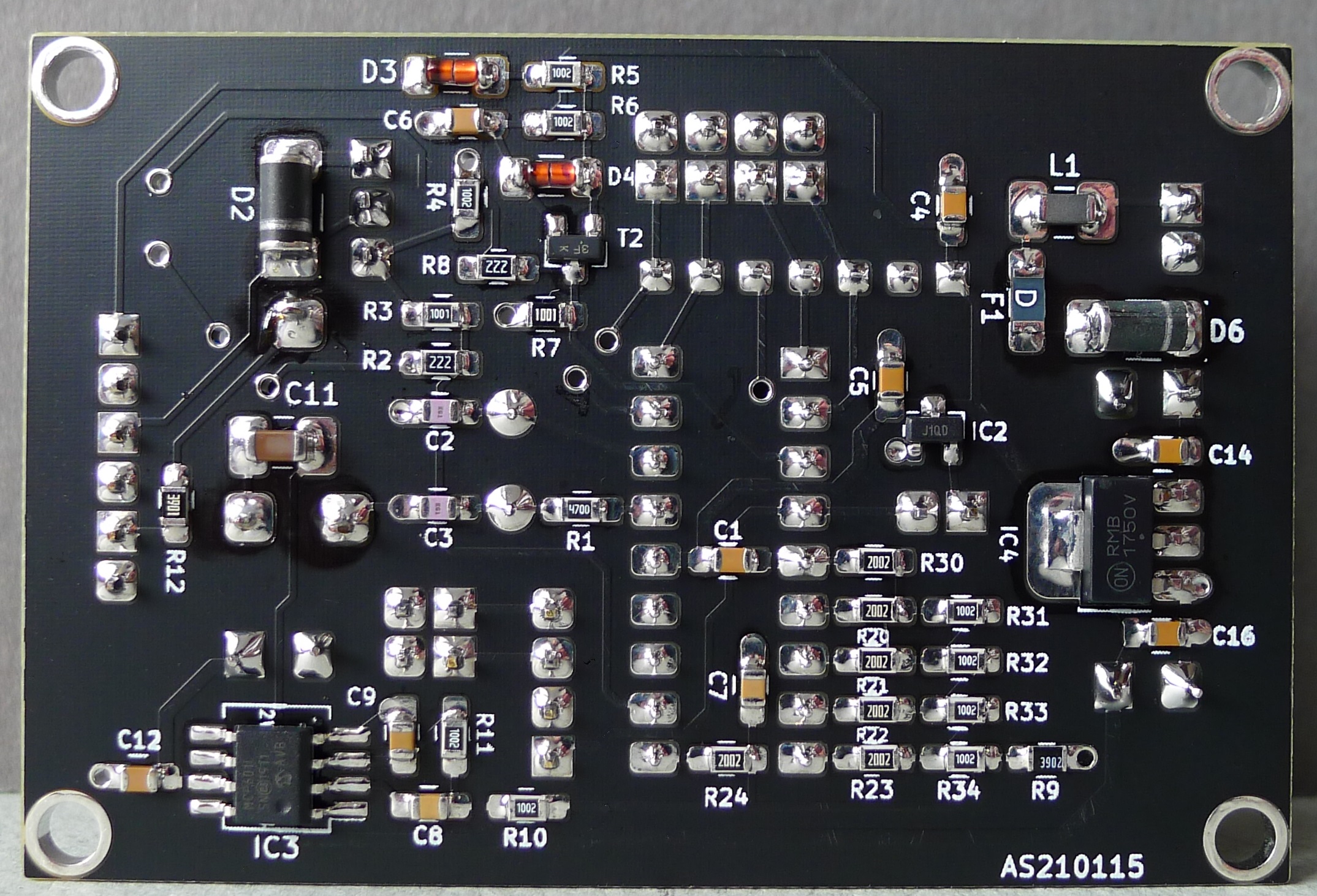
So, all the above led to the decision to drop the HW PTT hold time-limiter in the latest circuit redesign. Still, the main goal of the redesign of the nearly 20 years old project is actually not so much the well proven design to be improved as it is to replace the already obsolete components, which are nowadays hard to find and buy, by a more up to date and easy available electronic parts. Also due to low prices of the PCB prototyping in the recent years it probably doesn't make much sense and / or advantage making printed circuit boards at home so a decision of migrating to a double sided PCB design seemed like a logical step.
Although during all the years of gradual project development, many firmware versions have been released, most of them support the same basic functionality:
| detecting RX SQL. DET. condition, triggering the TX PTT as well as providing TX hold time delay, | |
| generating a "roger beep" signal after the RX reception drops out; there are 3 different "roger beep" tones provided to report different conditions of the RPT system, as describet below, | |
| the normal "roger beep" tone is a morse coded letter "I", signaling a normal repeater operation, | |
| the "roger beep" tone in a form of a morse coded letter "E" rather the "I" is being transmitted in a case of frequent RX drop outs, signalling the condition of a bad reception back to the transmitting station, | |
| a "roger beep" tone morse coded letter "B" rather the above mentioned "I" / "E" is being transmitted in a case of a main electric grid power supply drop out, signalling the repeater system is being powered from backup battery rather than main grid supply. The main power supply drop out is detected depending on the state of the JP6 jumper (shorted or open); please note that the JP6 is directly connected to the PIC microcontroller pin, without any ESD protection, therefore special care must be paid when using this input, | |
| generating a periodically transmitted morse coded ID message; the ID message replay period may be selected from several different values (15, 20, 30 or 60 min.) by the jumpers JP3 and JP4, | |
| delaying the morse coded ID message while the conversation is taking place on the repeater; the message is transmitted only after an on-going conversation is being stopped for a certain time (a delay time of 5 or 15 s may be selected through the jumper JP1), | |
| a continuous RPT transmission is limited to 10 minutes, the TX shutdown after the time limit has been reached is announced by a morse coded message "TX TIME OUT", | |
| a 2nd RX SQL detect input may be implemented at JP5 providing the RPT TX activation; no roger beep for 2nd RX so it can be to distinguished between the main and 2nd RX reception; please note that the JP5 is directly tied to the PIC microcontroller pin, without any ESD protection, therefore special care must be paid when using this input. |
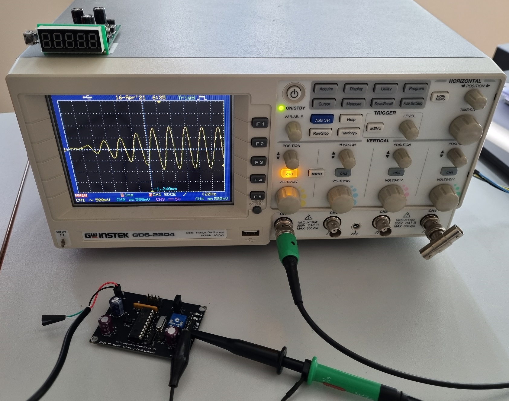
And last but not least, the ID message and other signalling tones are being generated and shaped as a pure sine tone with soft "on" and "off" edges resulting in a warm, "clicks free" as well as pleasent to listen to morse coded telegraphy (see the oscillogram on photo above).
Jumper settings
| JP6 | JP5 | JP4 | JP3 | JP2 | JP1 | |
| - | - | - | - | - | N.C. | ID message free delay - 2,5 s |
| - | - | - | - | - | SET | ID message free delay - 5 s |
| - | - | N.C. | N.C. | - | - | ID message replay periode - 15 min. |
| - | - | N.C. | SET | - | - | ID message replay periode - 20 min. |
| - | - | SET | N.C. | - | - | ID message replay periode - 30 min. |
| - | - | SET | SET | - | - | ID message replay periode - 60 min. |
| - | N.C. | - | - | - | - | 2nd RX = idle |
| - | SET | - | - | - | - | 2nd RX SQL. DET. active --> PTT activated (no "roger beep") |
| N.C. | - | - | - | - | - | "Roger beep" = morse coded "B" (backup battery power supply) |
| SET | - | - | - | - | - | "Roger beep" = morse coded "I" or "E" |
| Back to S56AL main page! |