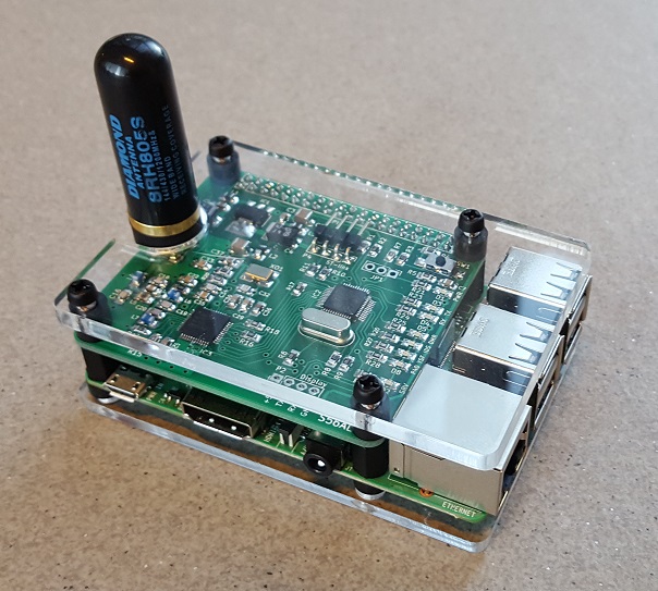
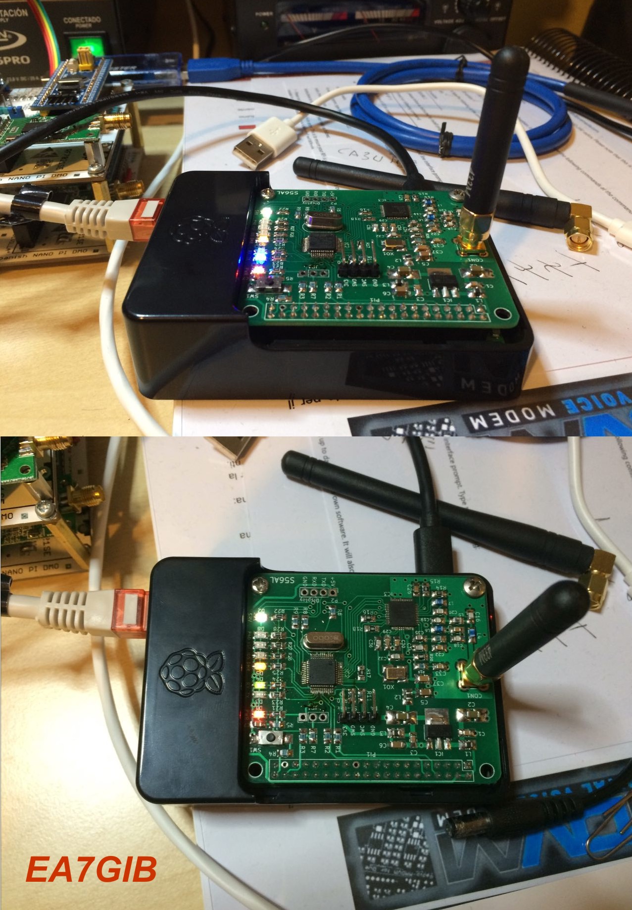
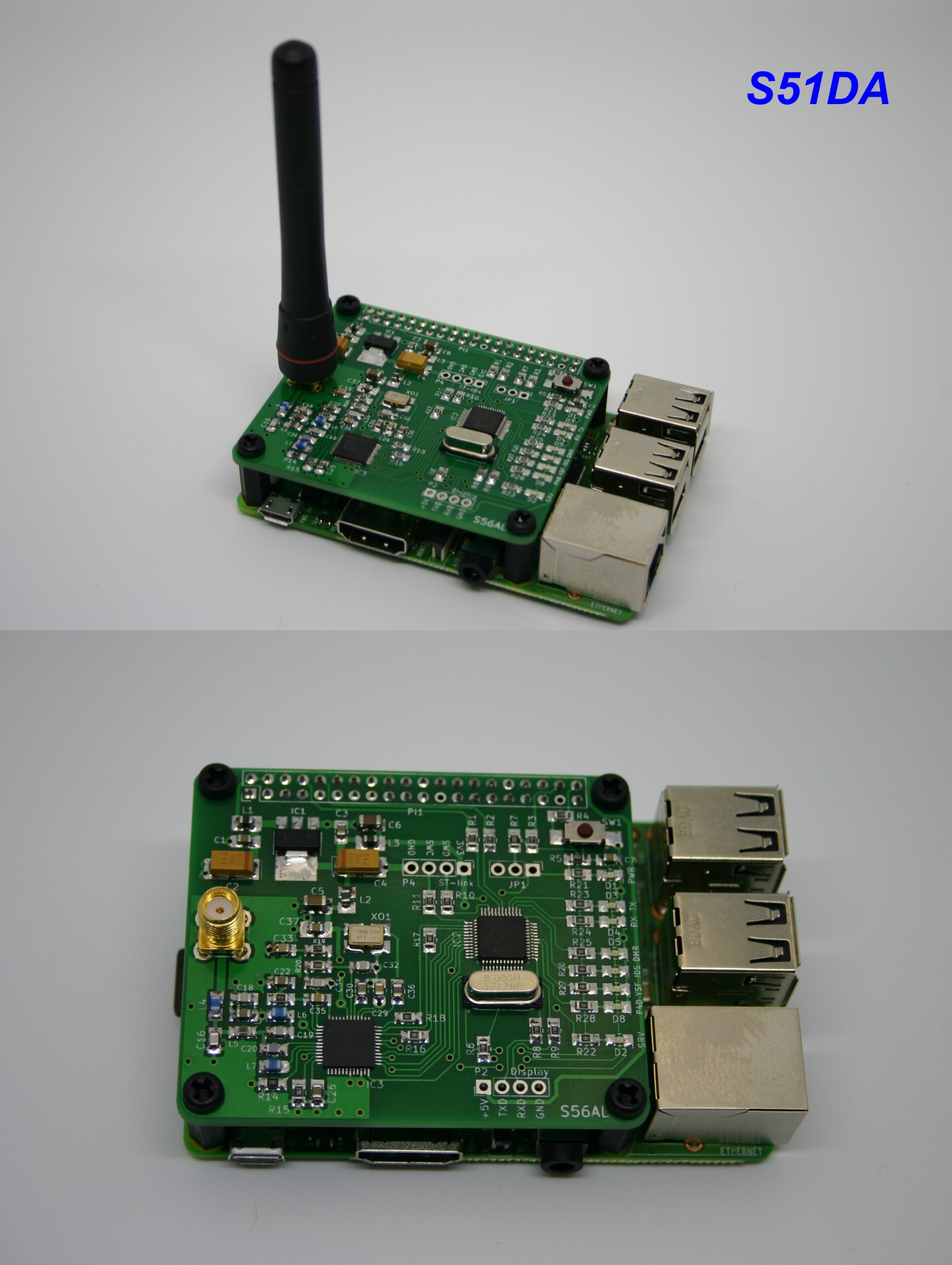
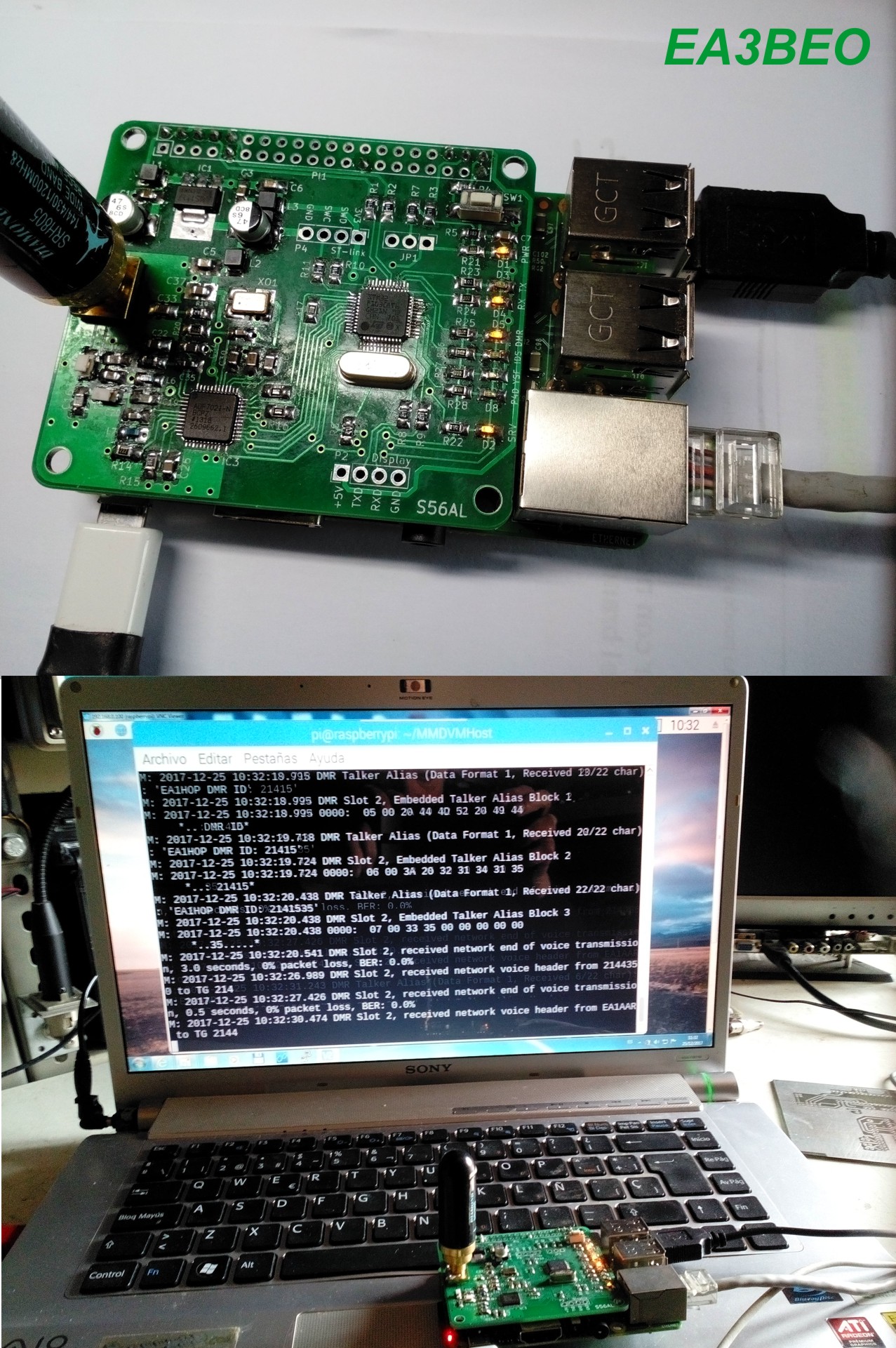
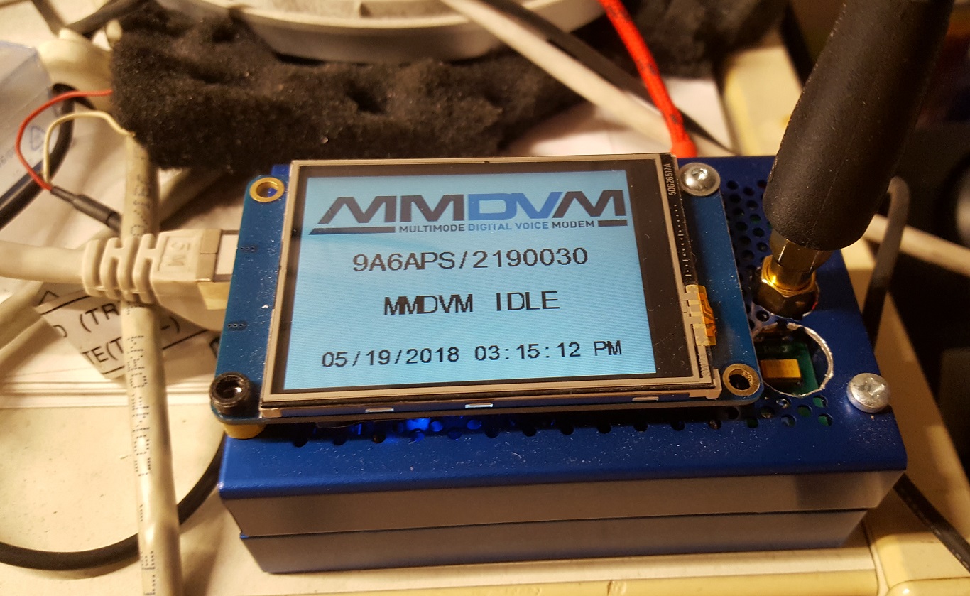
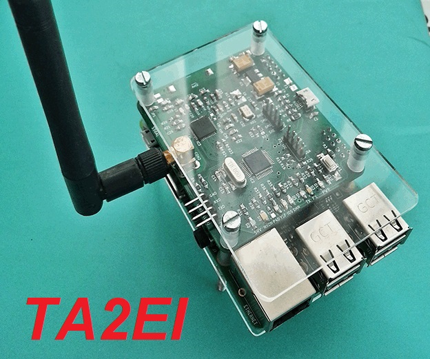
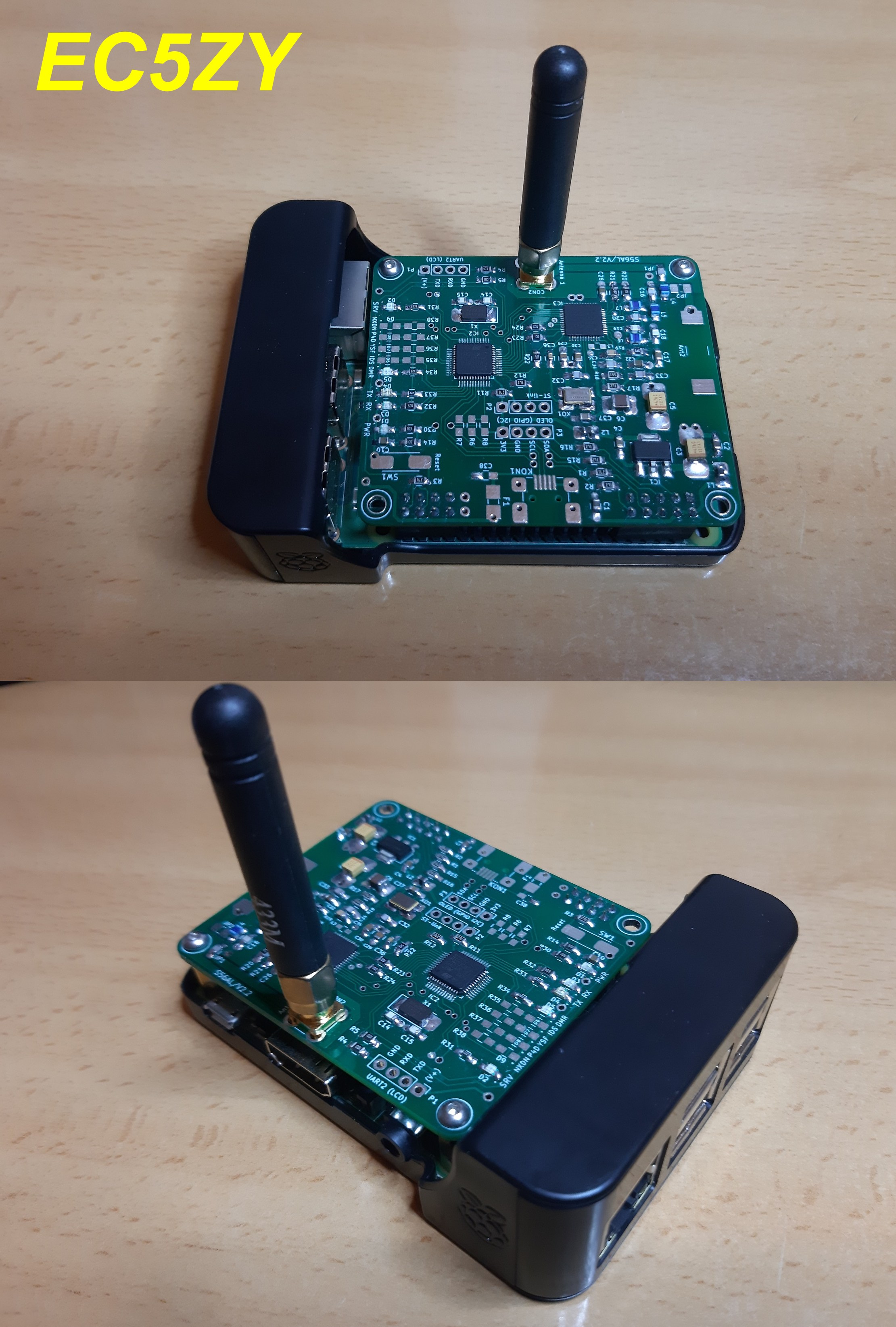
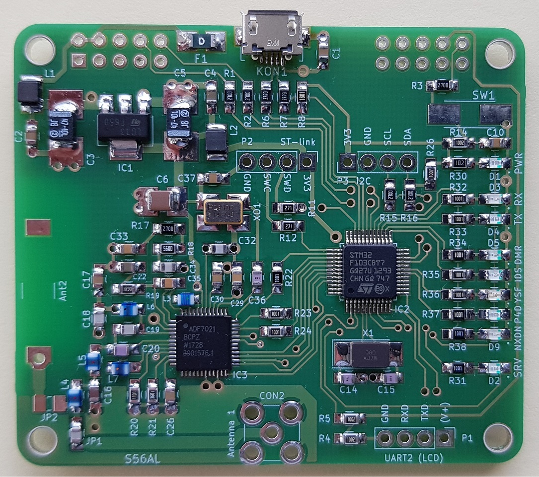
HotSpot units, built by Alfonso EC5ZY, Recep TA2EI, Damir 9A6APS, Gabo OK2UQL, Danilo S58DB, Paco EA7GWC, Tom ON4TOP, Jordi EA3BEO, David S51DA and Blas EA7GIB. Thanks to all for valuable feedback and contribution of the photos!
| |
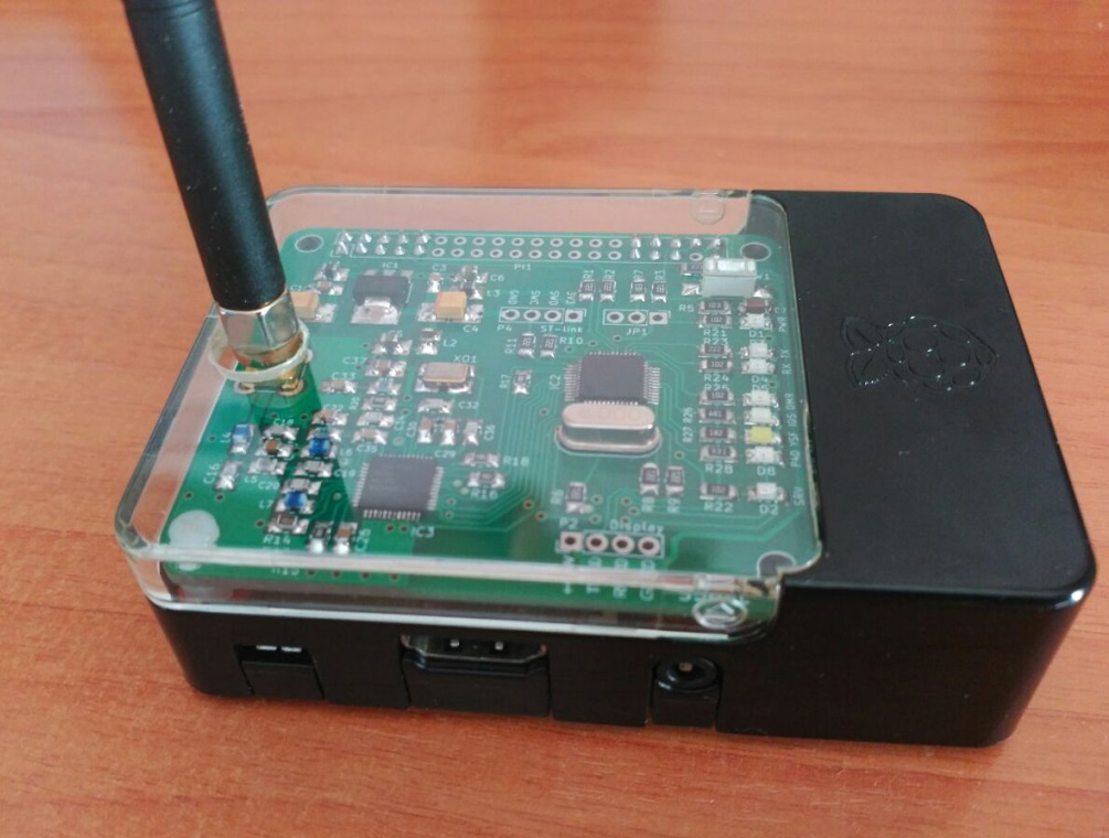
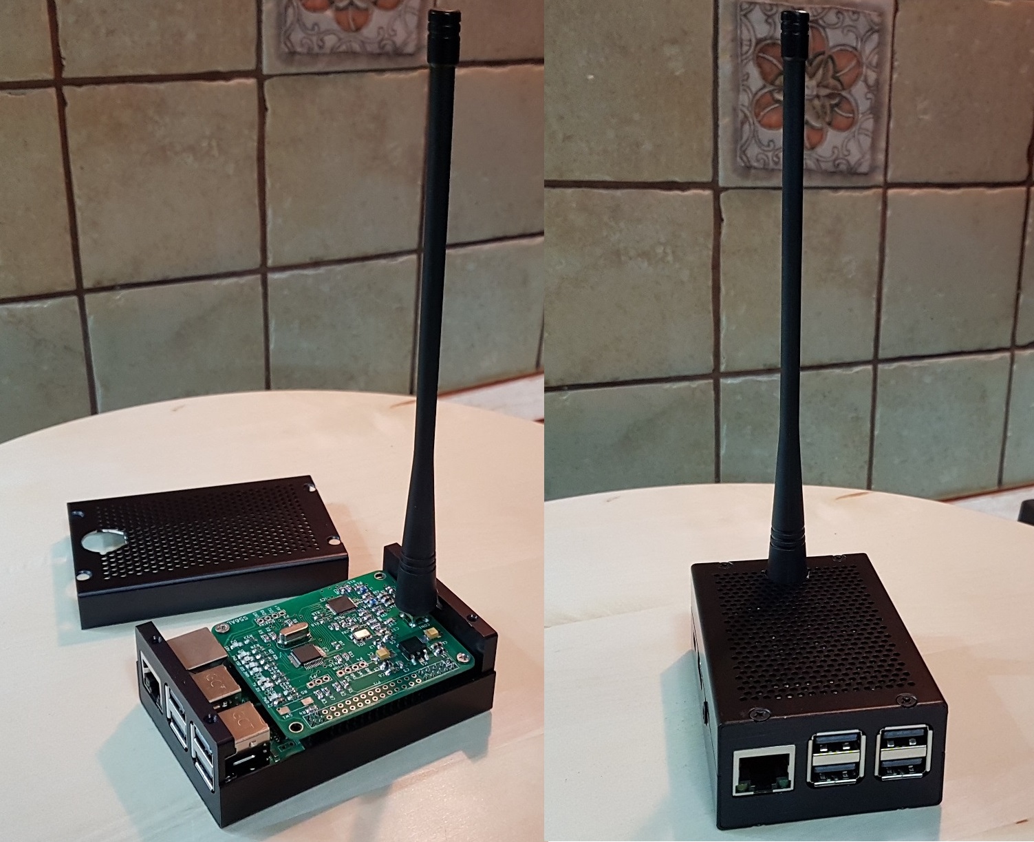
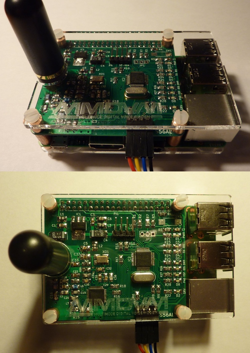
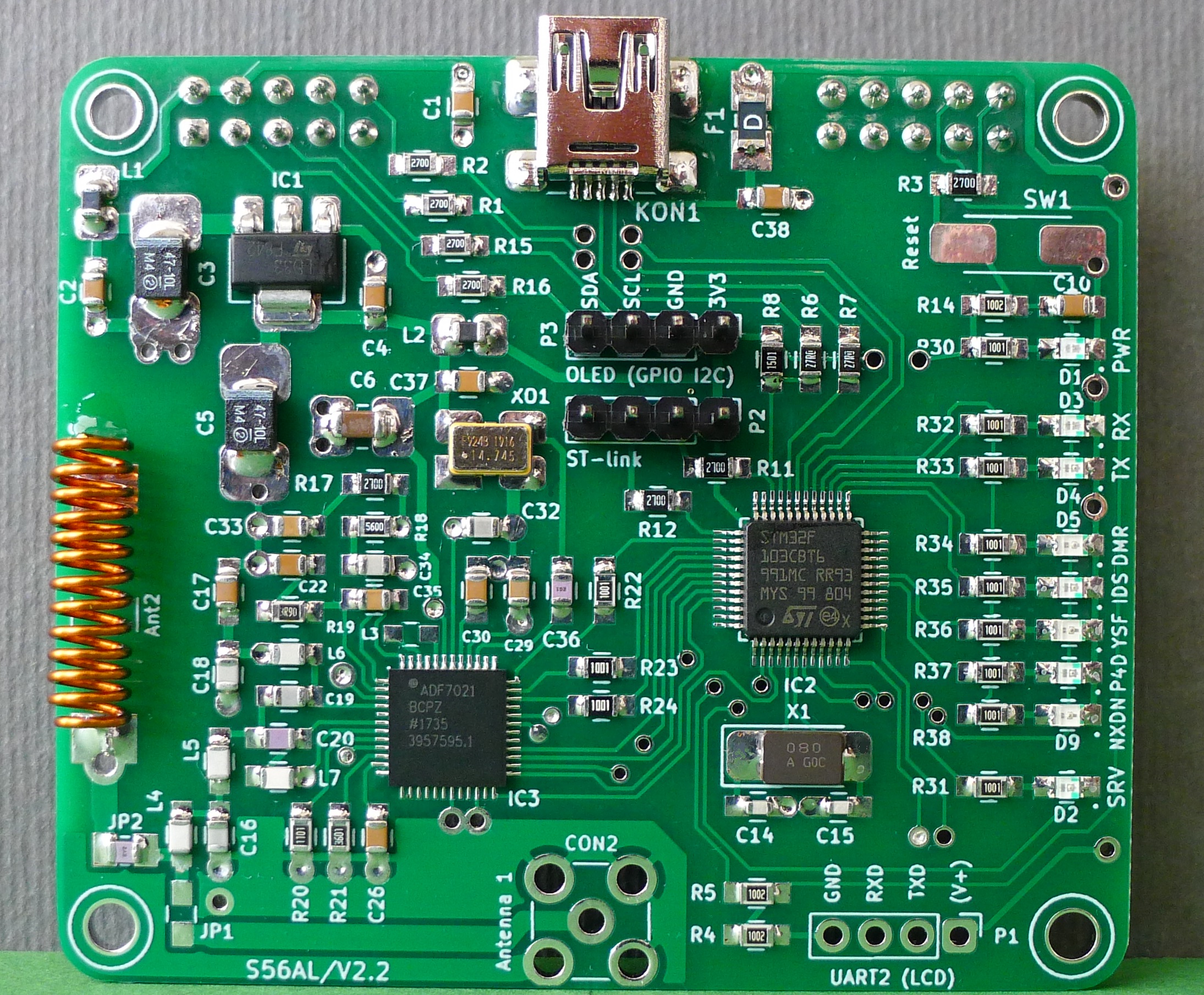
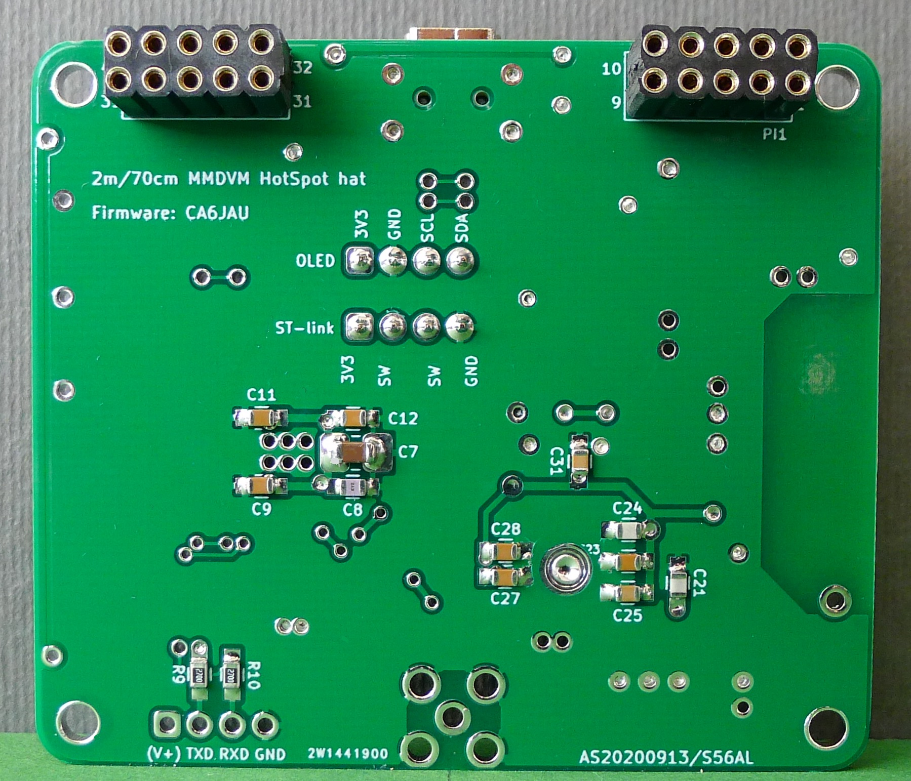
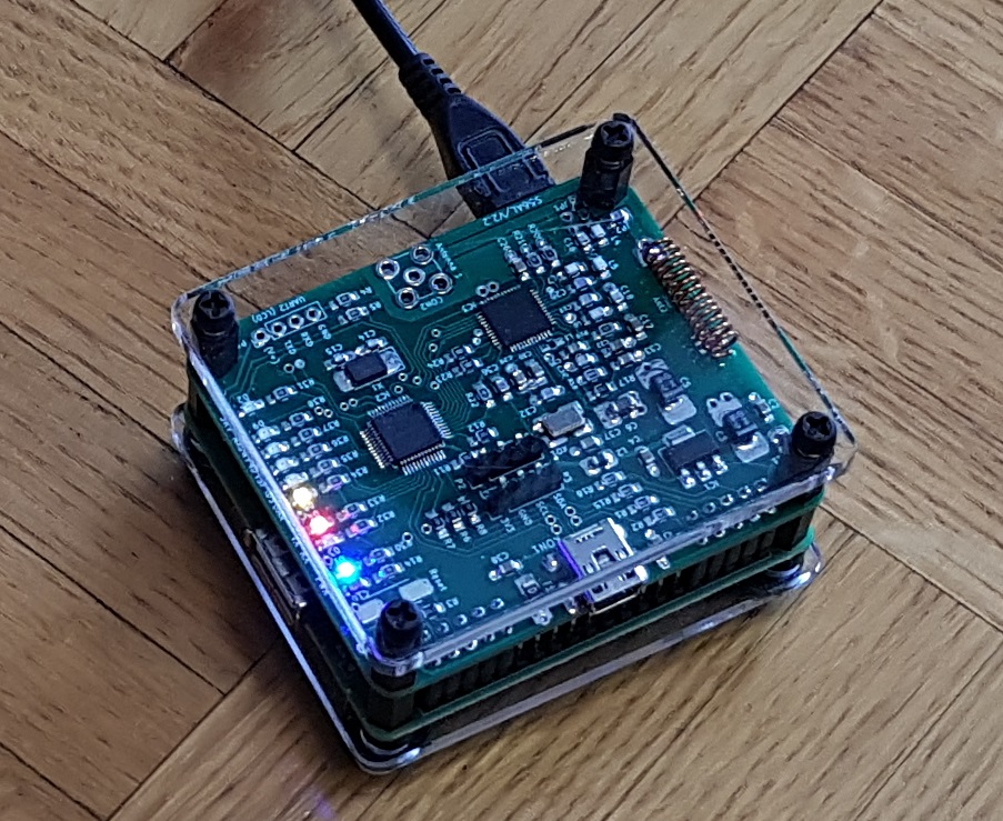
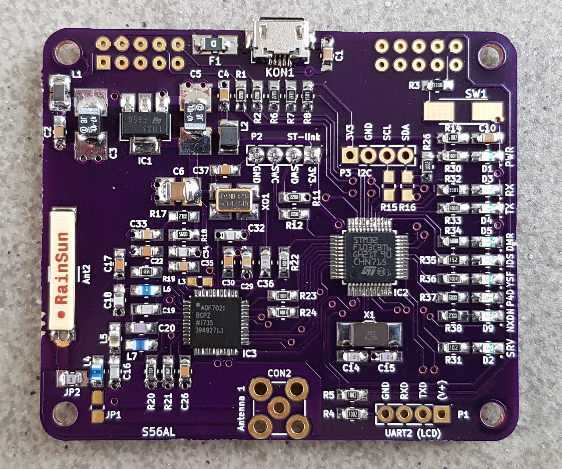
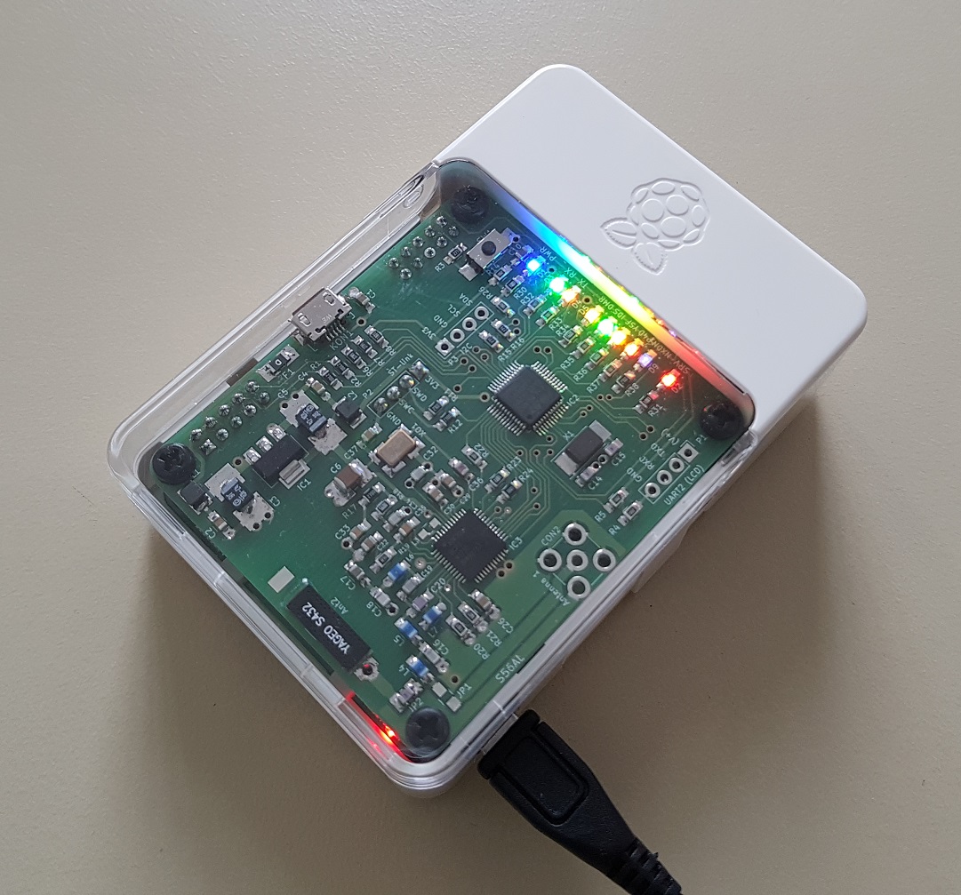
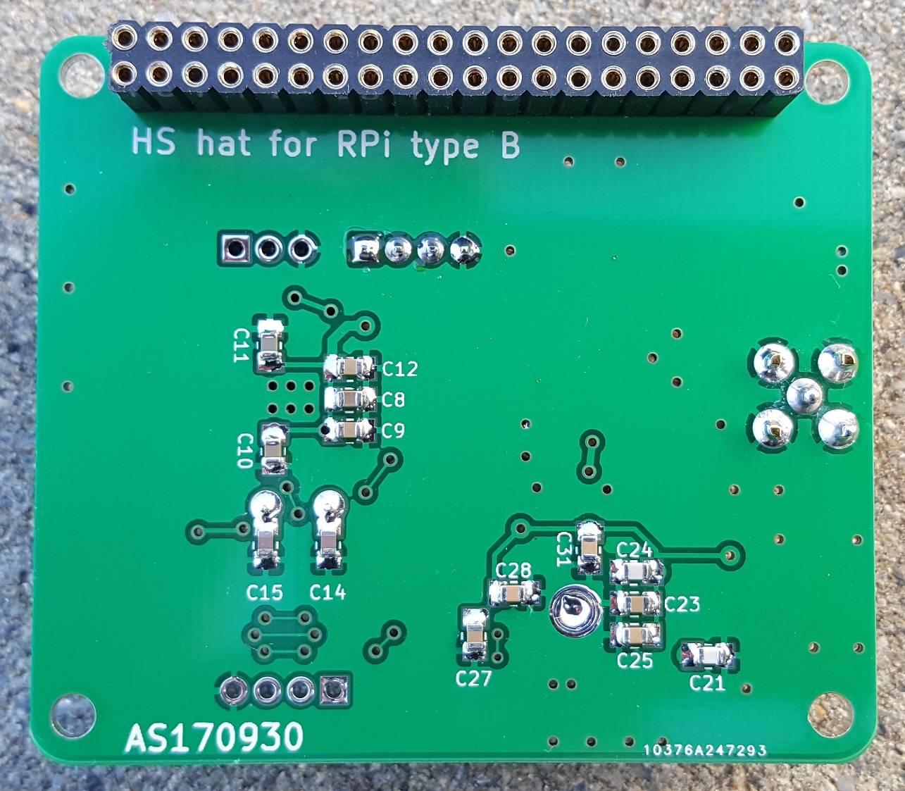
MMDVM HotSpot hat for RPi type B
Back to S56AL main page!
Click here if you are interested in building a dual (duplex mode capable) MMDVM HotSpot hat!
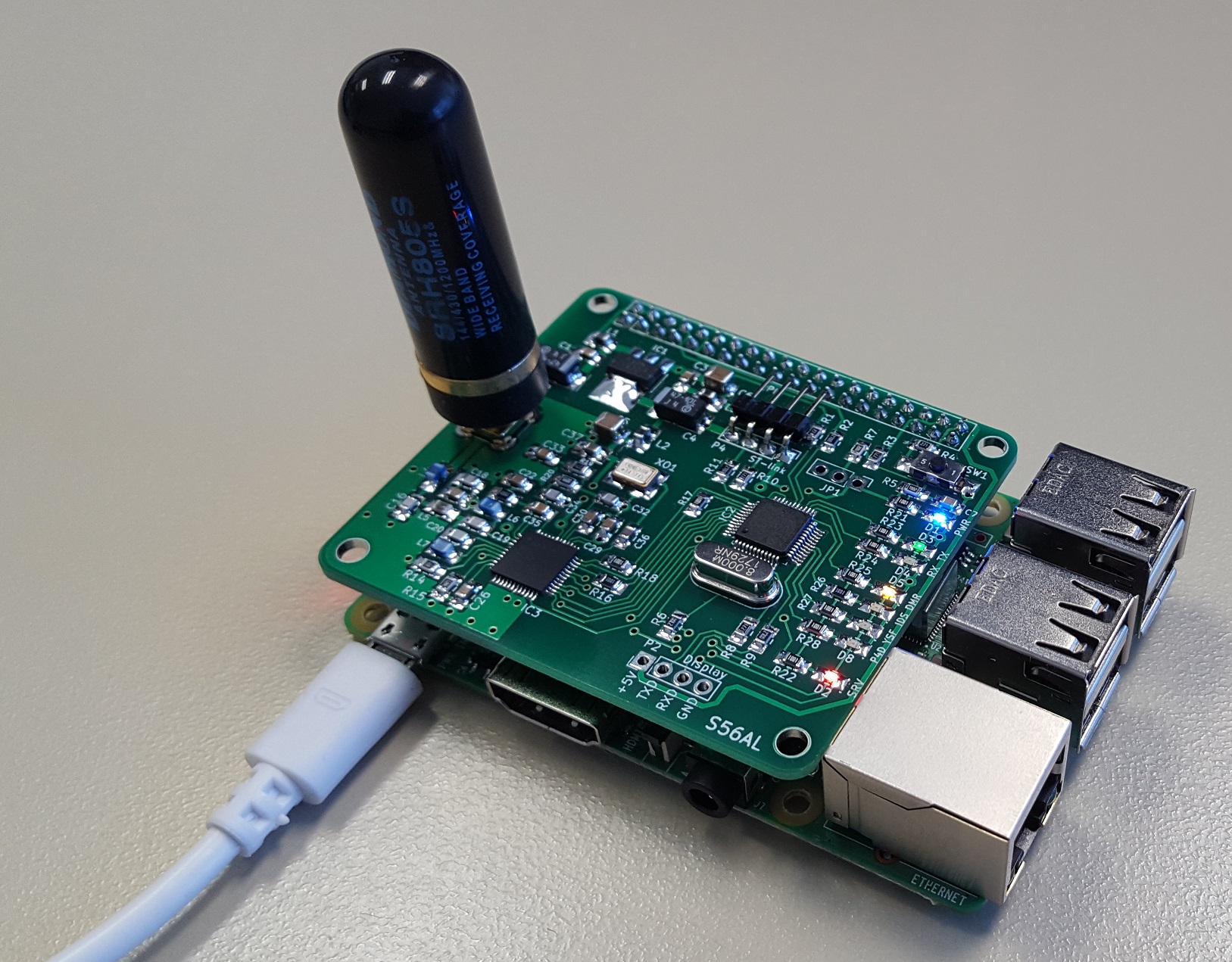
Version 2.0 released in March 2018, now supports VHF 2m operation as well as adds a possibility of USB connection to the host, NXDN LED and an on board "chip" antenna @ UHF 70 cm!
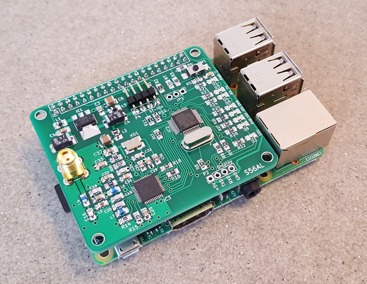
Implemented SMD components "0805" or bigger!
HotSpot units, built by Alfonso EC5ZY, Recep TA2EI, Damir 9A6APS, Gabo OK2UQL, Danilo S58DB, Paco EA7GWC, Tom ON4TOP, Jordi EA3BEO, David S51DA and Blas EA7GIB. Thanks to all for valuable feedback and contribution of the photos!
|
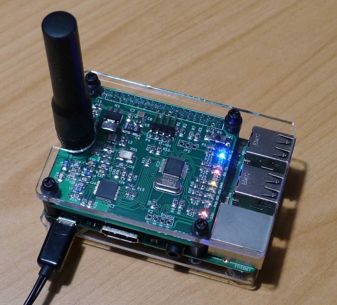
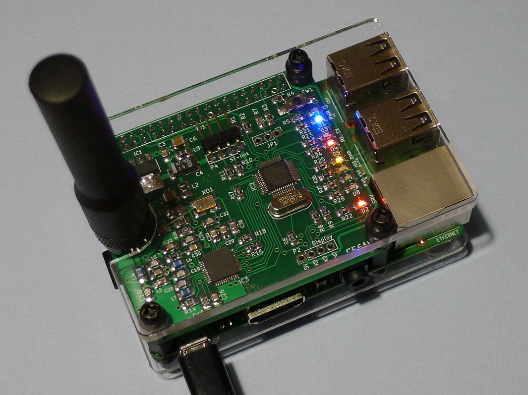
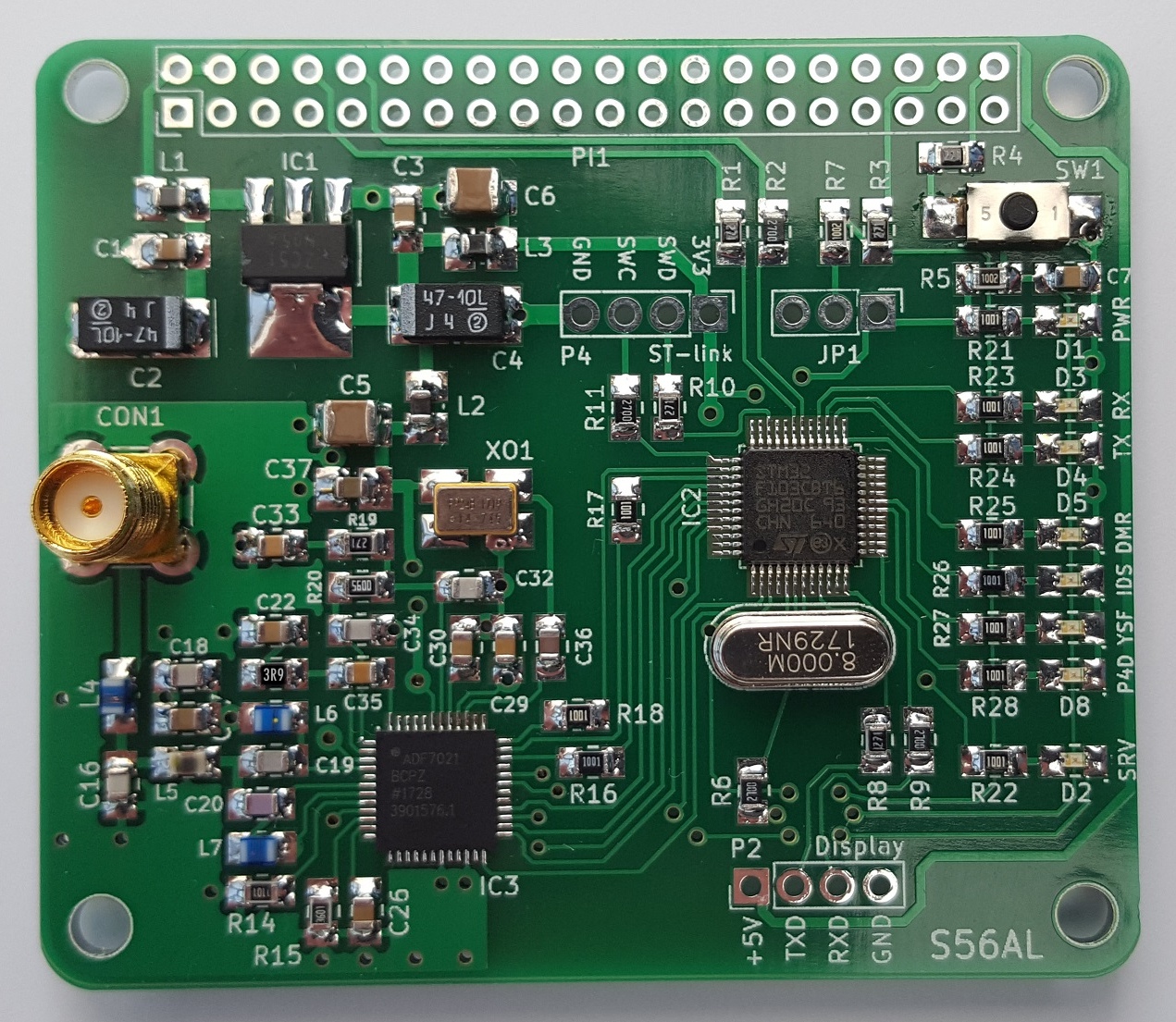
This page is about homebrewing an (almost) easy to build MMDVM HotSpot module for Raspberry Pi - type B.
After successfully finishing three boards of those wonderfull miniature HS hats for Rasbberry Pi-zeroW, designed by Mathis, DB9MAT and Florian, DF2ET , I have decided to draw a simmilar, however bigger HS hat board, that would fit a normal sized (type B) Raspberry Pi mini computer. Although a bigger size does barely mean an improvement when discussing HotSpot solutions, there is one big advantge - bigger board allows implementation of bigger and therefore easyer handleable SMD components.
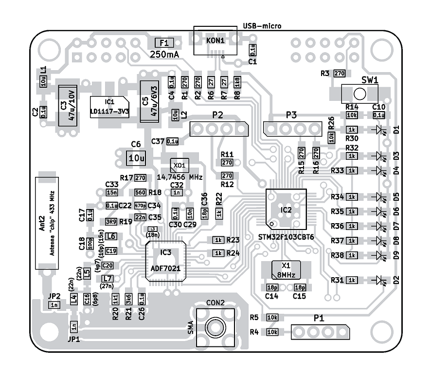
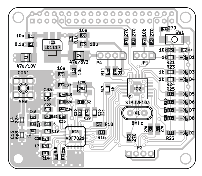
All resistors, capacitors, coils and LEDs used in this project are of the size SMD 0805 or bigger. This should make the assembly of the board much more frendly to a homebuilder who only has access to an average equiped amateur workshop. Furthermore the pads of SMD components are also dimensioned in somehow excessive size to allow more comfortable hand soldering even by a not so experienced builder.
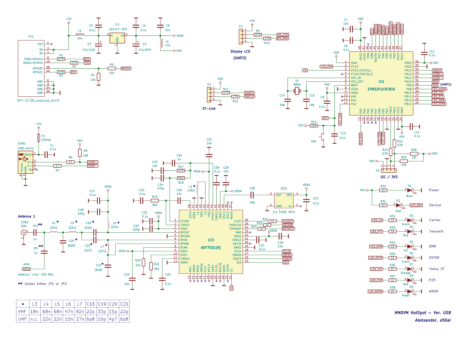
However, some basic level of hand soldering skills is still recomended for a successful assembly of the HotSpot module board. There is one critical component that requires a bit of experience to be soldered correctly: the RF chip ADF-7021. Mainly due to unpleasant pad configuration at the botom edge of the package rather than because of it's so called "exposed pad", as one might think. The later is easily solderable to the ground through one huge (3mm dia) via placed just under the bottom of the ADF-7021 chip.
As mentioned above, this board is not a good starting point to learn SMD soldering. However, if you insist on building this circuit despite insufficient SMD soldering skills, consider two important things: FLUX IS YOUR BEST FRIEND and EXCESSIVE AMOUNT OF TIN IS AN ENEMY!
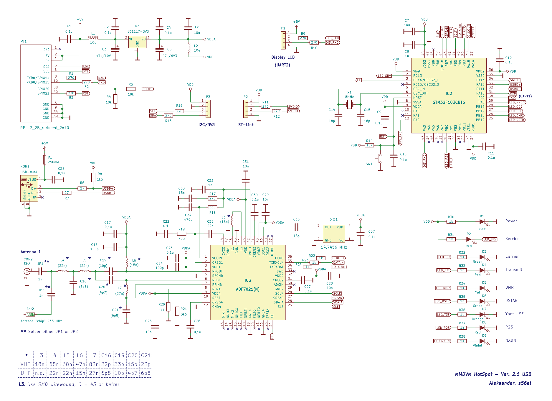
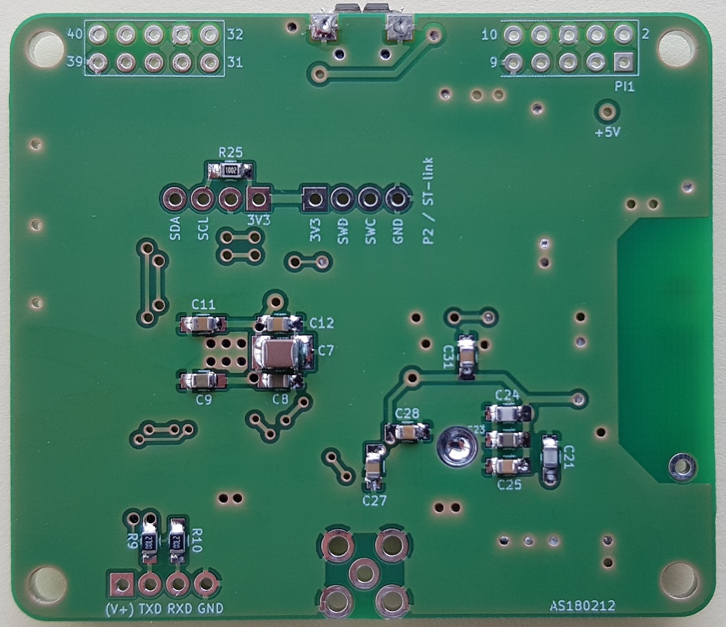
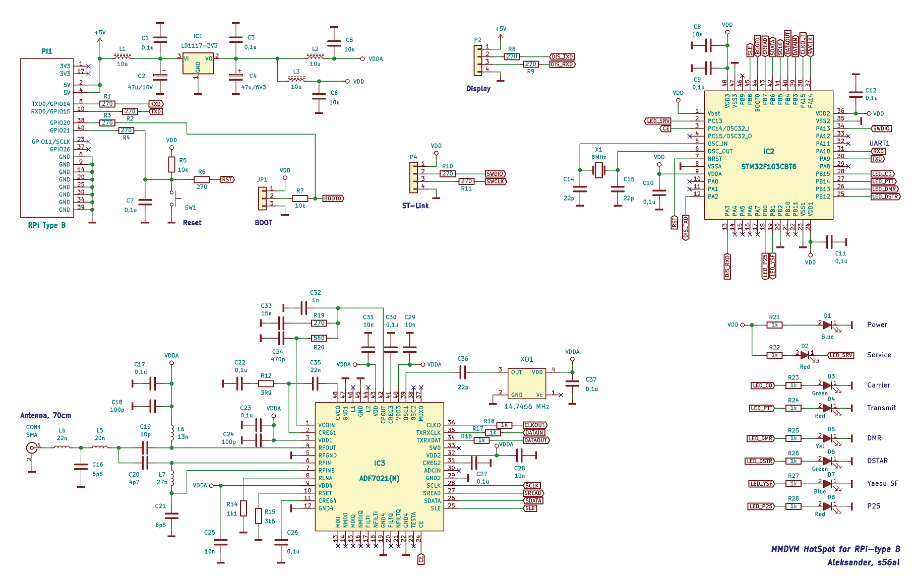
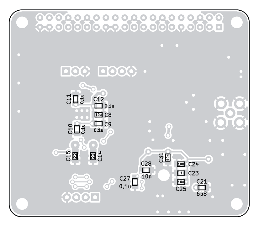
Although originating from similar circuit configurations (ADF7021 + STM32F103) of other authors, I have added some small improvements to the circuit. All power supply pins of the ADF-7021 are blocked with capacitors strictly as proposed by the manufacturer and described in the IC's datasheet. Other than that there is an on board 5 V to 3,3 V linear voltage regulator as well as additional separate RF blocking for both IC's 3,3 V supply branches by 10 uH chokes and 10 uF / 25 V ceramic capacitors. This should positively contribute to lowering the RX BER in case of supplying the HotSpot by those miniature, usually heavily noisy (switching) 5V socket power supply adapters (phone chargers).
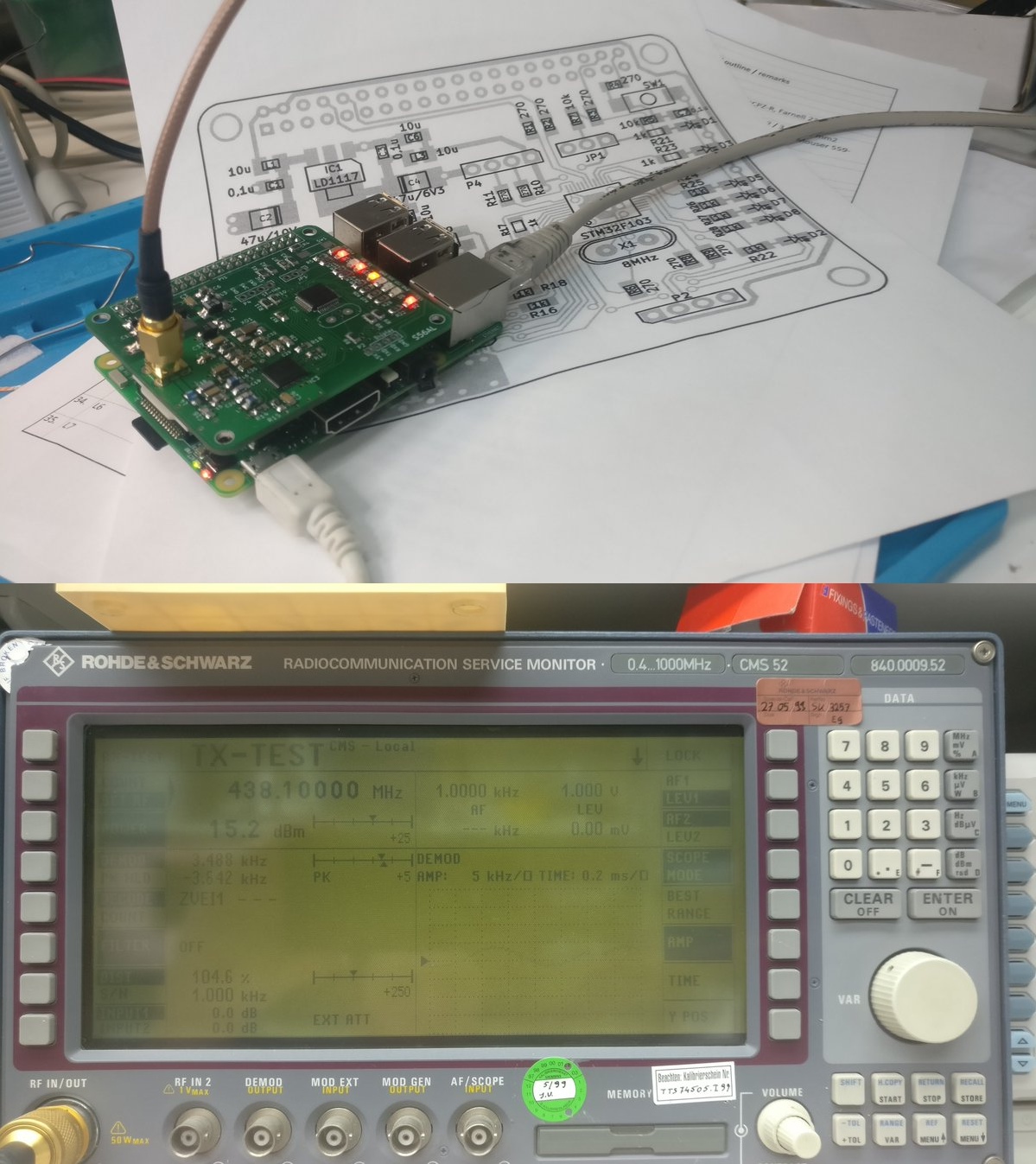
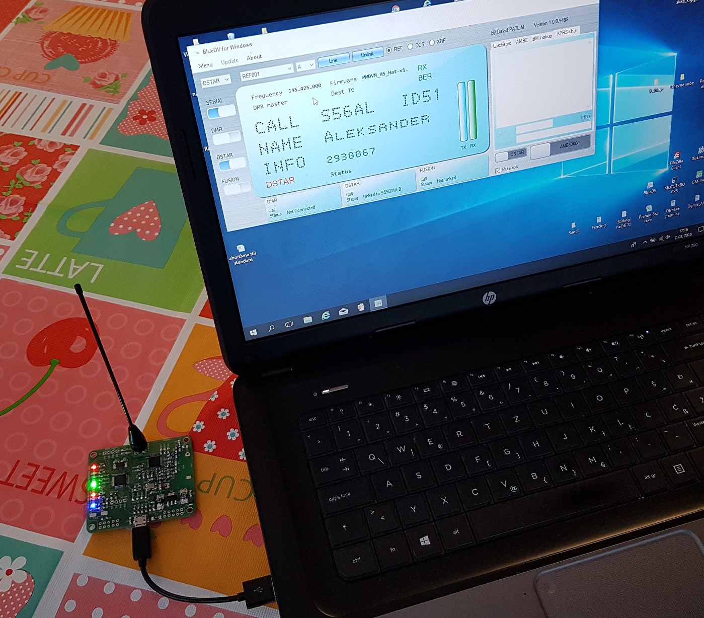
For further information and instructions on programming the neccessary firmware into the STM32F103 microcontroller, please visit the José Andrés, CA6JAU's GitHub page as well as his video (Tutorial instalación ZUMSpot Pi) at YouTube. The video is highly informational regarding the downloads, compilation, upload and installation of all the necessary software packages to the RPi and HotSpot board, including the MMDVM software, written by G4KLX .
Version 2.2 - release September, 2020
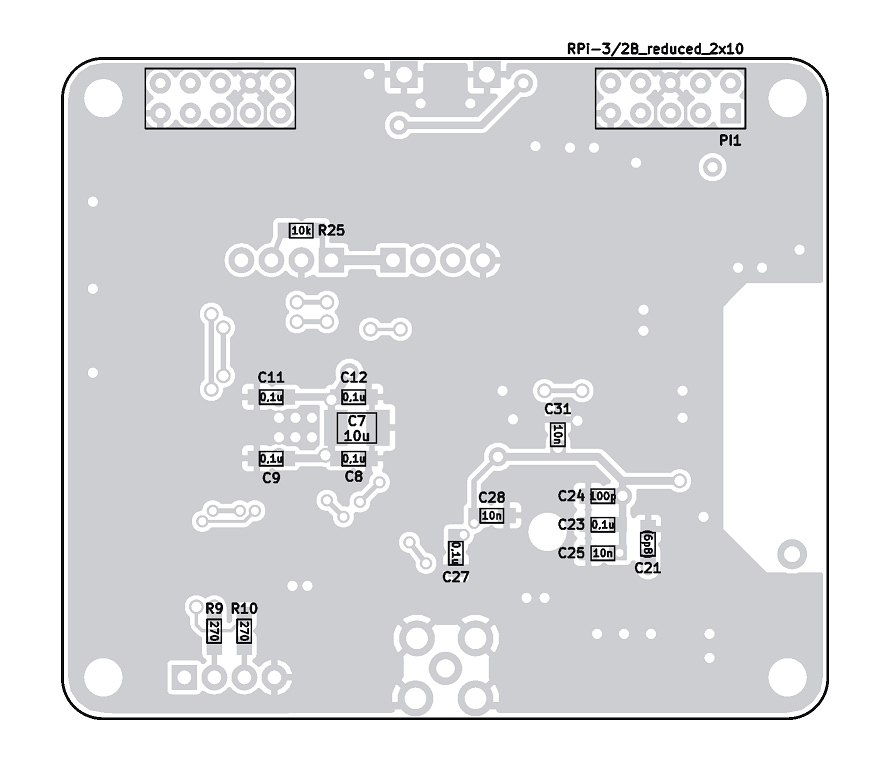
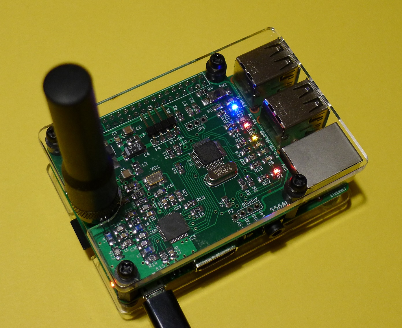
The updated simplex HotSpot hat version 2.2 introduces a direct I2C (OLED) header connection to the coresponding RPi GPIO header pins, a more robust "Mini USB" connector type fitted to the PCB as well as the +5V pin of the LCD header fed from the RPi GPIO +5V pins directly.
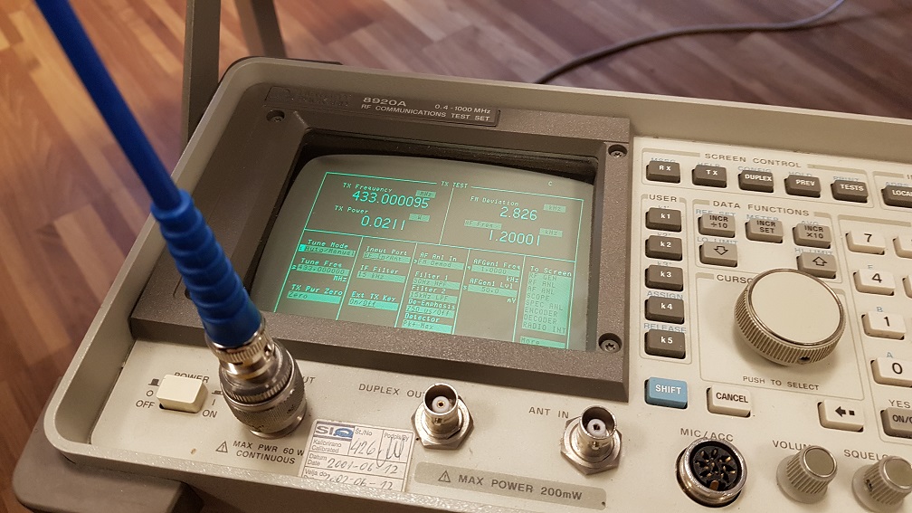
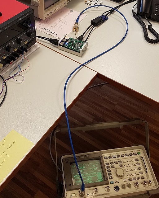
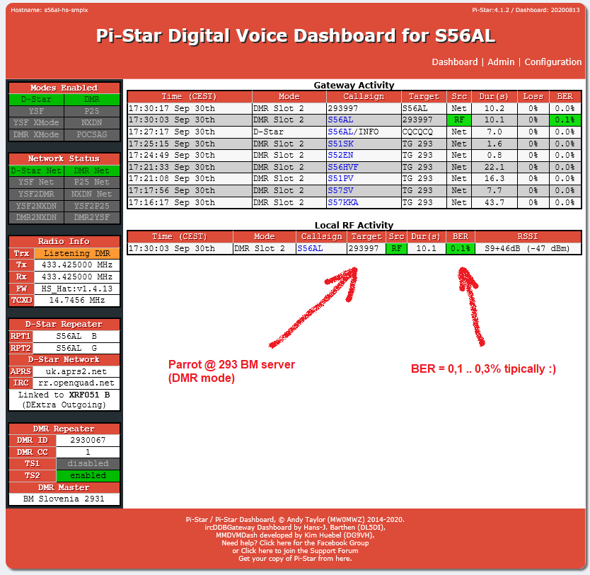
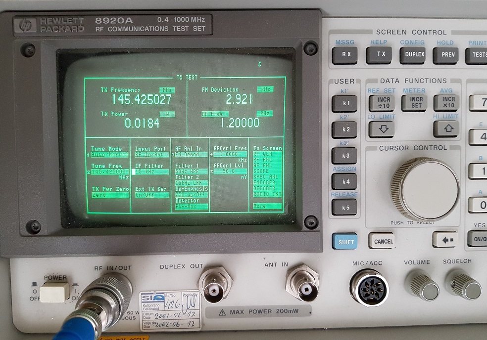
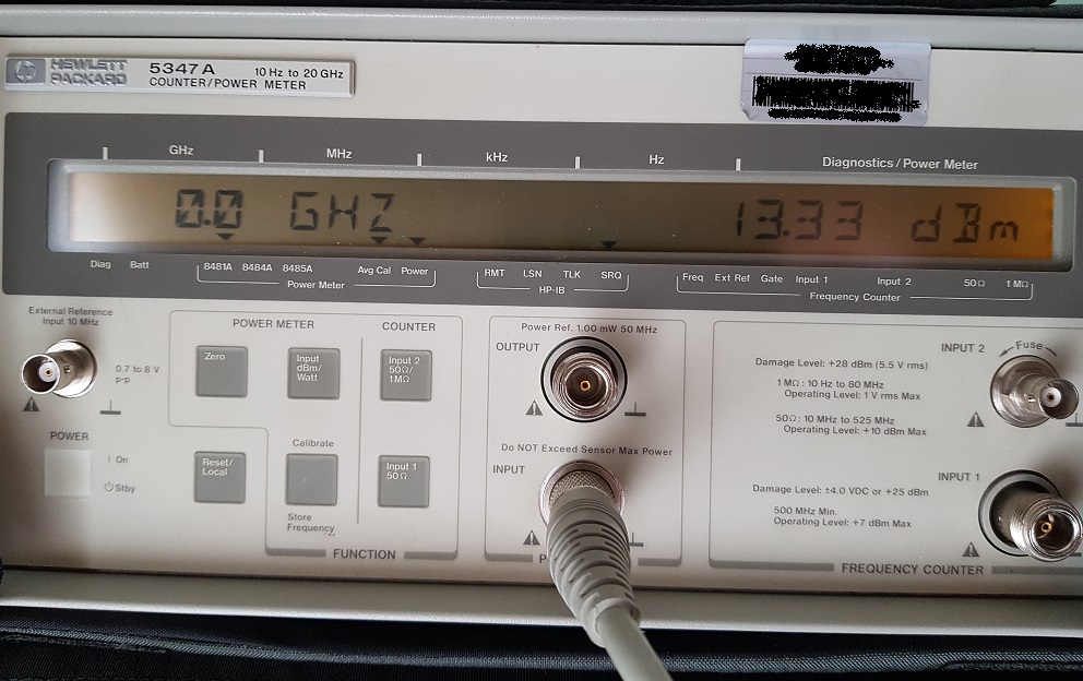
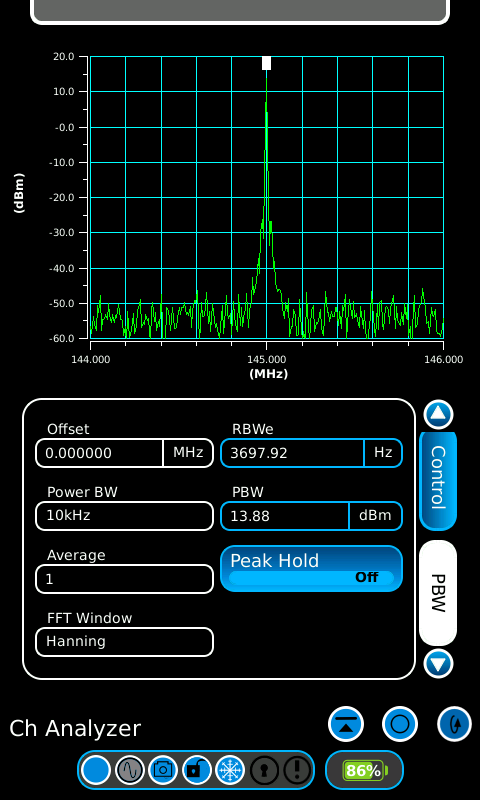
I would also like to point out few other things. Please use a quality 14.7456 MHz TCXO. With the suggested FOX-924B type you can not go wrong. It is available for about 3 EUR from Farnell or Mouser as well as other suppliers. I have built well over 50 instances of the simpleks and duplex HS hats so far, always using the above mentioned TCXO and never found one that would cause the frequency to deviate more than 100 Hz from it's nominal value in the 70cm band (or 30 Hz in the 2m band). Also never needed to adjust the frequency "in the software" to rectify the so called "BER problem" while maintaining the BER in the DMR operation mode in a range between 0,1 to 0,3 % (as well as zero BER in D-STAR).
The optional L3 coil that enables the ADF-7021 2m band operation if installed should be selected from SMD wire wound types with a Q factor of at least 45 or better. A cheaper SMD multilayer type may be used for L4 to L7. The SMD multilayer coils have a Q factor value of about 20 tipically (although there may be significant differences between different multilayer types) and introduce only a minor detorioration of the TX output power and RX sensitivity compared to the wire wound coils.
 |
 |
 |
 |
 |
 |
 |
 |
 |
| Ver. 2.2 - Bill of materials (13 kB - xlsx MS Excel) | Ver. 2.2 - PCB - Gerber files (109 kB - zip) |
| Compiled firmware (bin) - RPi GPIO / UART1 (31 kB - zip) | Compiled firmware (bin) - USB (43 kB - zip) |
Version 2.0 - release March, 2018
The new version 2.0 now supports VHF 2m operation, adds USB connection to the host as well as an "on board" alternative 70cm "chip" antenna. There is also an additional LED to identify the recently added NXDN operating mode. Still friendly to build by using SMD components of the size 0805 or bigger. SMA antenna connector has been moved to the longer edge of the PCB.
Many thanks to Blas EA7GIB for all the suggestions and inspiration regarding new features as well as Jose Andres CA6JAU for helping me clarify some USB connection and other firmware / compiling related issues.
 |
 |
 |
 |
 |
 |
 |
 |
 |
 |
 |
 |
 |
| Ver. 2 - Bill of materials (15 kB - xlsx MS Excel) | Ver. 2 - PCB - Gerber files (63 kB - zip) | RSSI measurement @ 2m VHF (1 kB - txt) |
| You can also order three high quality PCBs from OSH park prototyping service here! | |
Version 1.0 - release November, 2017
 |
 |
 |
 |
 |
| Hišni HotSpot MMDVM - Podroben opis s slikami v slovenskem jeziku (različica izdaje 6. 12. 2017, pdf - 2 MB) | |
| Back to S56AL main page! |