| Turn a professional 2m VHF FM PMR
transceiver Motorola Radius M110 into an amateur radio Modification by Beno S56KZN and Aleks S56AL |
W A R N I N G - All modifications described on this page are performed to your own risk. Authors can not overtake any responsibility of any sort of the possible damages that would result from unskilfully performed modifications, described on this web page.
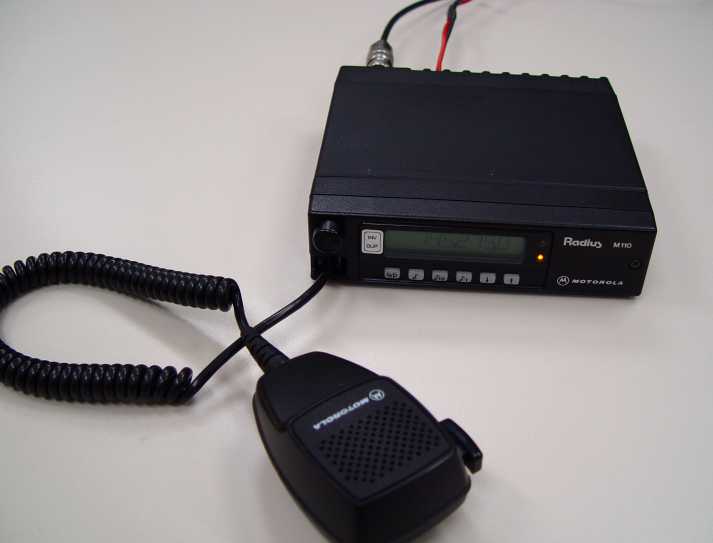
The PMR VHF transceiver Motorola Radius M110 (in further text referred as M110) was manufactured by Motorola GmbH therefore being an European radio. Since many professional radio service users has replaced this transceiver with newer gear, a considerable number of M110 has appeared on HAM flea markets. M110 is a simple yet fine transceiver with pretty good receiving performance and it would be a waste to throw it away or to use it just as a source of electronic components instead of giving it a new life in the HAM shack.
Check a photo of the modified radio , the new functionality of the display and front pannel keyboard functions
For additional information on Motorola Radius M110 please visit also http://www.batlabs.com/micro.html
The modification described on this page is not just a reprogramming of the existing 9 channels of the M110 to HAM frequencies. It is a hardware upgrade that will turn the PMR transceiver into a full-featured HAM transceiver. After the modification has been done the transceiver supports following functionality:
| Coverage of the complete European 2m HAM band 144.000,0 kHz ... 145.987,5 kHz | |
| Available tuning steps: 12,5kHz, 25kHz and 100 kHz | |
| Repeater (-600) kHz and inverse repeater (+600 kHz) operation | |
| 1750 Hz repeater tone | |
| Automatic setting of the repeater offset when the frequency is changed, later it can be manually switched to the inverse repeater, repeater or simplex mode | |
| Display of the operating frequency in a 7 digit mode, for example 145.787.5 | |
| Memorising of the latest set frequency and tuning step during power down | |
| Replacement of the "ears-breaking" key-clicks with a more gentle click tones and elimination of the "strokes" when squelch opens /closes | |
| Measurement and display of the supply voltage in 0,1V resolution | |
| RF characteristics of the transceiver are kept unchanged |
The idea of the modification was to use as much of the existing hardware as possible. Three modification concepts were examined. Probably the most elegant way to "improve" the radio would be to obtain and modify the source code of the main board microcontroler MC6302 firmware which takes care over the functionality of the M110. Another although more time consuming method would be to write a completely new firmware. Unfortunately both concepts would require an access to at least an emulator of the 6302 single chip microcontroler plus availability of the firmware in first case and complete detailed schematics of the circuits in the second case. Neither of this was available to me. The 6302 is a pretty old microcontroler which (as far as I know) doesn't exist in a FLASH program memory version that would allow a development of the firmware with reasonably simple and cheap tools.
The only way found to be realizable was to analyse the communication between the M110 main and display unit microcontroler, break this communication and insert an additional hardware module that would use existing display /keyboard unit as a man-machine interface, outwit the main processor and control the PLL chip.
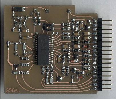
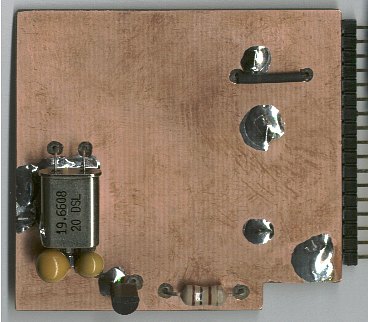
The new hardware unit, inserted in the communication path between main and display unit, should therefore provide two UART interfaces, one serial synchronous peripheral interface (SPI) to control the PLL chip and some additional stuff to produce man-machine interface tones (key-clicks) and 1750 repeater tone. It bases on a single chip PIC16F876 microcontroler. This controller has only one hardware UART interface so the 2nd one is implemented in software. PIC16F876 supports also only one interrupt priority level. That is why a pretty high system clock oscillator frequency of 19,66 MHz was chosen to keep the generated 1750Hz repeater tone fairly clean. Otherwise the module could operate at much lower oscillator frequency (like 4,9152MHz). The module is built on a double sided PCB, one side of the board serves as a ground. Most of the implemented components are SMD. This allows the installation of the module in the bottom compartment inside of the M110 housing.
| Circuit schematic | PCB assembly | Photo - Top view | Photo - Bottom view | HEX code, V1.0 | PCB - 600dpi, gif |
Preparation for hardware upgrade
Before the modification is performed it is strongly recommended to program the 9 existing channels of the original M110 to amateur frequencies, equally spread over the complete 2m HAM band and carefully tune the RX VCO, TX VCO as well as RX and TX resonant circuits as described in the service manual or concentrated alignment instructions prepared by Beno S56KZN (2.3MB). When this is done and transceiver is radically tested (specially with the frequencies at the both band edges), reprogram the transceiver with the parameters needed to run modified radio.
Hardware upgrade
1. Remove the display unit and aluminium top cover from the transceiver body.
2. Remove the plastic cover from the display unit (no screws, only rubber holds it in place :).
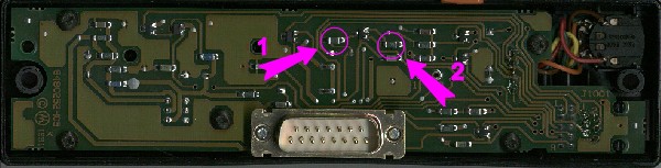
3. Locate the 820Ohm resistor (see arrow 1 - photo of the display unit) and desolder it. This turns off the horrible key-click tones generated by the display unit processor.
4. Locate the 10 Ohm resistor (see arrow 2 - photo of the display unit) and replace it with short circuit or another resistor with value <1 Ohm. This would allow you to control the speaker audio level with the potentiometer down to zero.
5. Put the plastic cover back to it's place on the display unit.
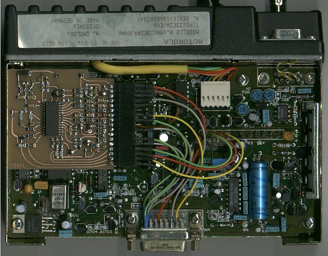
6. On the main processor board locate and unscrew 9 screws that hold this board in place. Two are at the side of the housing (chassis), holding the power transistors cooler attached to the chassis. The screws are of different lengths so remember which one was where. Unplug the connector that connects the TX power amplifier to the board. The board removes easier if the two screws that hold TX power amplifier at the back of the transceiver are slightly untightened. The main processor board is connected to the PLL / RF board at the other chassis side with a fairly strong header. GENTLY pull the board together with the header from its place with the help of a wider screwdriver (without sharp edges) or better with a suitable wooden or plastic tool inserted between the board and metal chassis as close to the header as possible.
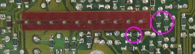
7. On the bottom side of the main processor board locate three 4,7 kOhm resistors (connected to the 2nd, 3rd and 4th pin of the header) and remove them (see main board, bottom side). This disconnects the PLL chip from the main board microcontroler. Put the main processor board back to its place and screw it down.
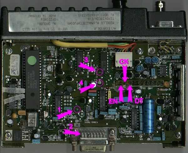
8. On the top side of the main processor board locate the trace from JU805 and cut it (arrow 1 - main board, top side).
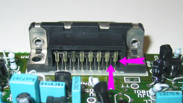
9. The UART (communication) connection between the main and display unit microcontrolers leads through the pins 8 and 15 of the 15-pin (DB15) connector. Cut this two pins approx. at the middle (arrows - DB15 connector and arrow 2 - main board, top side). Later four wires will be soldered to this two pins at both - display and main board sides.
10. Insert the built module to its place (see the picture upgraded main board). Connect the header at the module PCB edge (see PCB assembly) to the main board with 14 wires as specified in the table.
| HEADER | Connection to the main board |
| +12V | Parallel to the pin 13 of the 15-pin DB15 connector |
| GND | To the ground of the main board PCB - find a strong suitable ground area somewhere on the main board close to the module header and connect with the shortest possible wire |
| NFOBL | Parallel to the via marked with "R" (arrow 4 - main board, top side) |
| MMIT | Parallel to the pin 3 of the 15-pin DB15 connector |
| T1750 | Parallel to JU805 |
| PTT | Parallel to the pin 2 of the 15-pin DB15 connector |
| MBTX | To the pin 8 at the main board side of the 15-pin DB15 connector |
| +5V | Requires no connection, this is just a spare source of the regulated 5V supply voltage, may be used for other purposes |
| MBRX | To the pin 15 at the main board side of the 15-pin DB15 connector |
| DISRX | To the pin 8 at the display side of the 15-pin DB15 connector |
| DISTX | To the pin 15 at the display side of the 15-pin DB15 connector |
| PLLEN | Parallel to the pin 2 of the header that connects the main board with the PLL board (arrow "EN" - main board, top side) |
| PLLDT | Parallel to the pin 3 of the header that connects the main board with the PLL board (arrow "DT" - main board, top side) |
| PLLCK | Parallel to the pin 4 of the header that connects the main board with the PLL board (arrow "CK" - main board, top side) |
| LDDIS | Parallel to the pin 16 of the CA3081 (arrow 3 - main board, top side) |
11. Isolate the inner side of the aluminium housing top cover at the place where the module is inserted with a paper or similar isolating means (Scotch tape).
12. Put the housing cover and the display unit back to their place, connect the transceiver to the antenna (or dummy load) and to the power supply. Connect the loudspeaker and the microphone.
13. Turn the transceiver on. The operating frequency should be displayed and the yellow LED should light. If the transceiver responds when the keys are pressed, try to press the mic. PTT key. The red LED should come on and the transmitter should transmit.
14. The modified transceiver is ready for it's first QSO.
| Back to S56AL page! |