6:4 non-Blocking HF/VHF Switch Matrix
1. Modes of operation
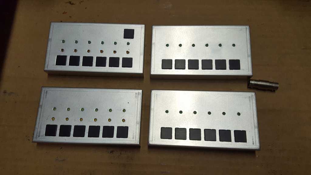
Selection of 6 antenna inputs to each one-out-of-four RX output is controlled by a set of 6 buttons (see photo below)..
HF mode (mode where 4 receivers/operators can select any of 6 antennas):
- each of 4 operators or receivers (in case one receiver is SDR
used for CW skimmer, for example) controls its own antenna selection
- pressing button N selects N-th antenna
VHF mode (mode where 2 operators with dual-receivers each select a combination of two antennas):
- first operator controls antennas for RX1 and RX2
- pressing button 1 selects A1 to RX1 and A2 to RX2
- pressing button 3 selects A3 to RX1 and A4 to RX2
- pressing button 5 selects A5 to RX1 and A6 to RX2
- pressing button 2 selects A2 to RX1 and A1 to RX2 and the same logic stands for buttons 4 and 6
- second operator controls antennas for RX3 and RX4 in a similar manner
Auto-rotate function alows for automatic antenna selection
in cyclical order after PTT has been released (one can select how many
antennas are being used for auto-rotate function).
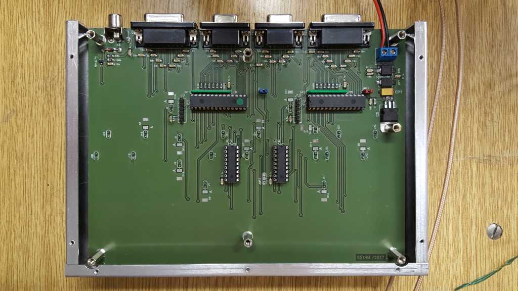
2. Few photos
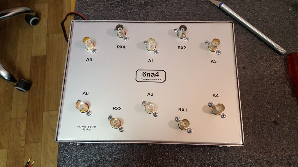
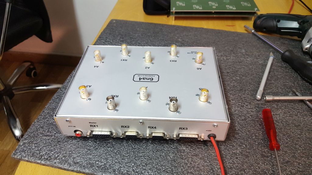
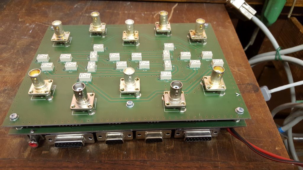
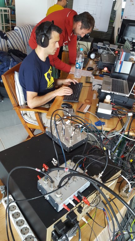
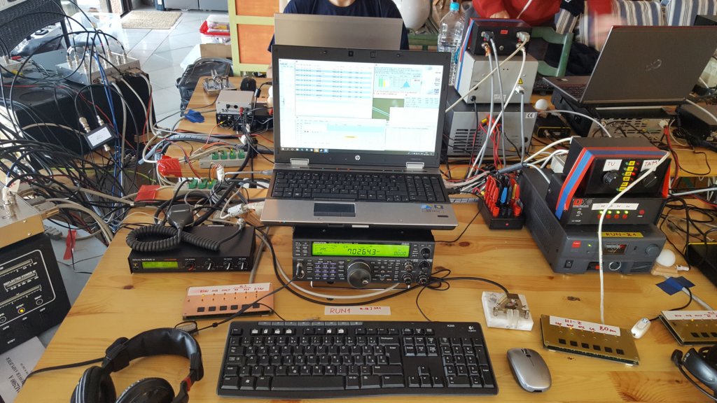
TK0C M2 CQ WW DX CW 2017.
3. Technical data
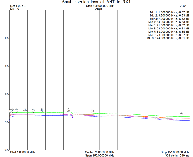
Insertion loss.
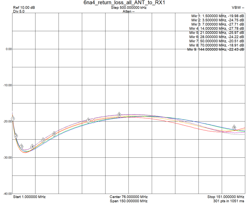
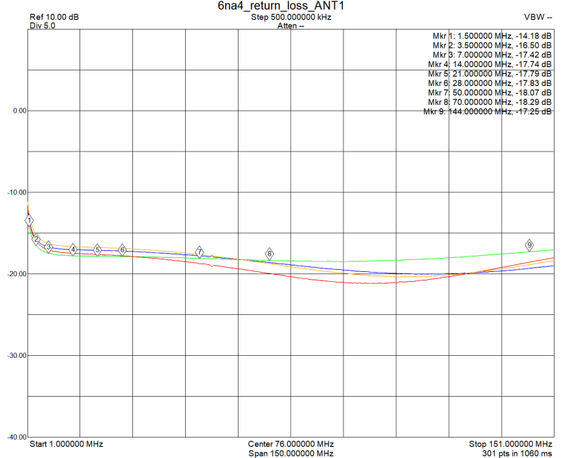
Return loss.
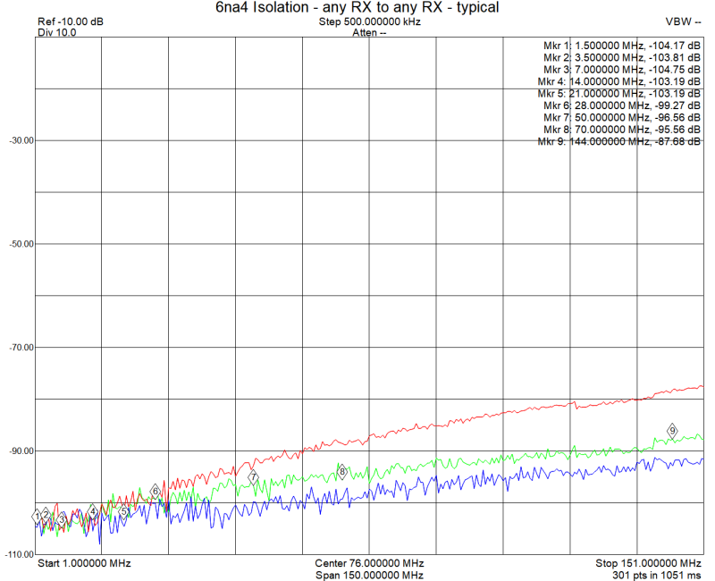
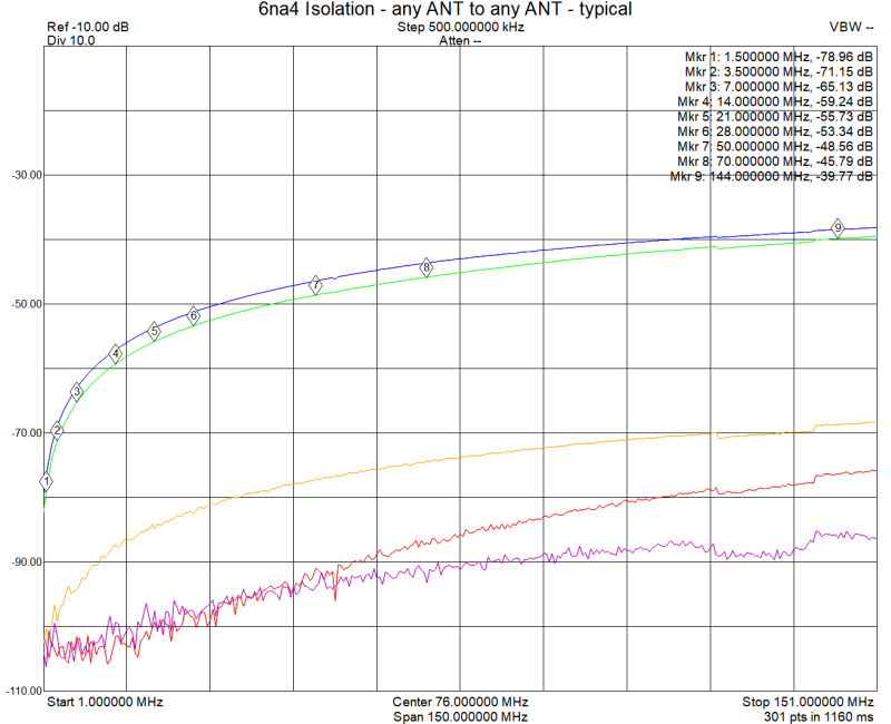
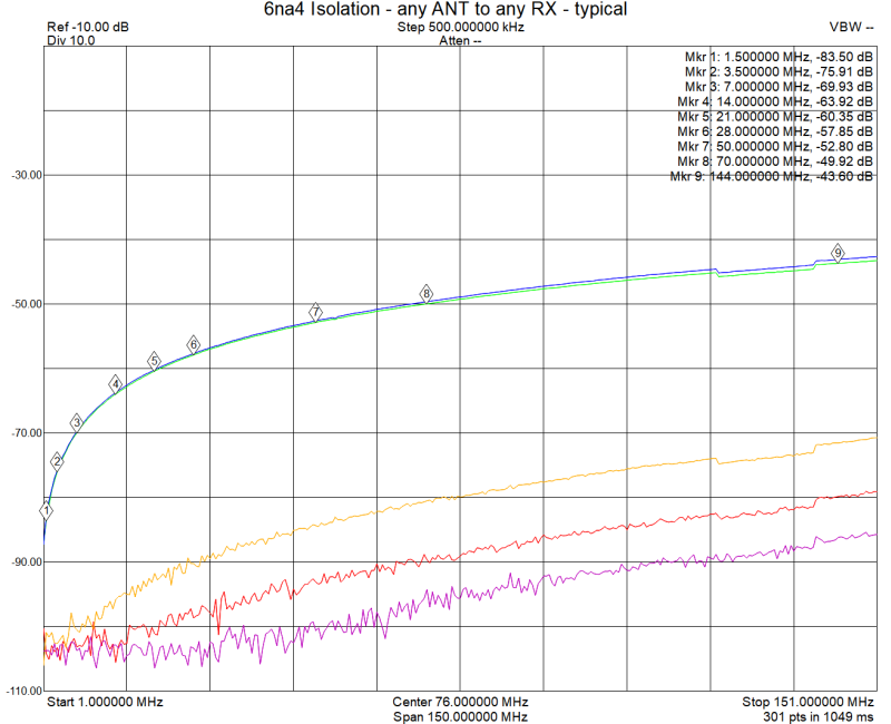
 Isolation.
_____________________________________________________________________________
Date published: Dec. 2017
Change log:
- Aug 2018: added performance data


 Isolation.


