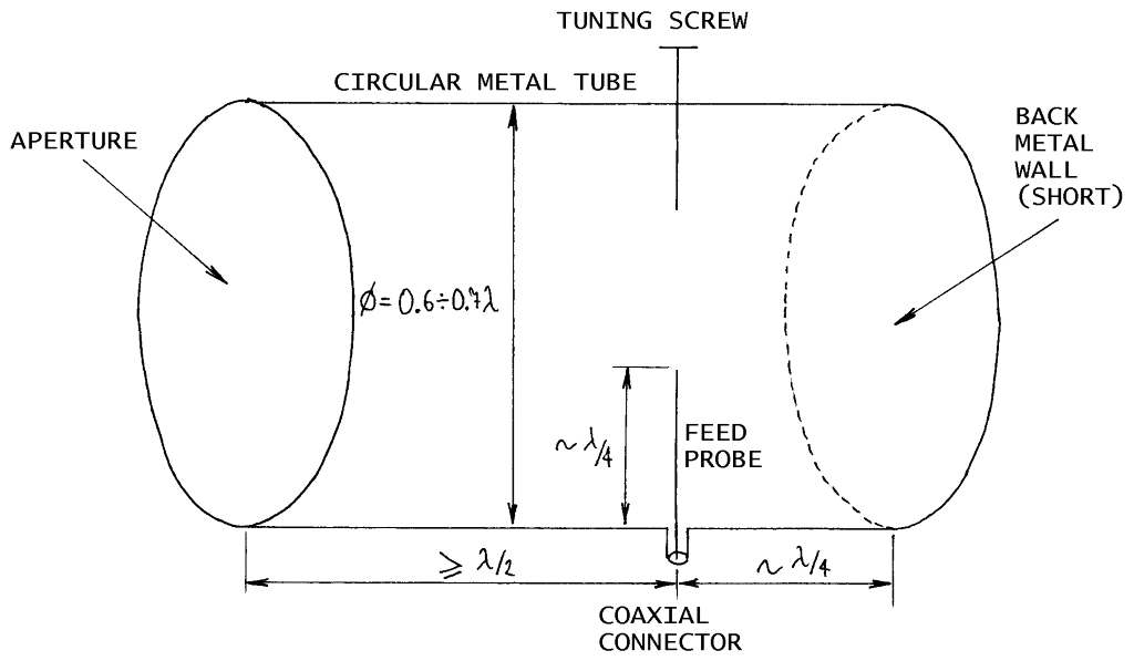
Fig.2.1.1 - Circular-waveguide-horn design.
(CAVITY)
(HORN)
(CUP)
(SBFA)
(ARCHERY)
(SELECT)
(HOME)
Weatherproof UHF & microwave cavity antennas
Matjaz Vidmar, S53MV
2. Circular-waveguide horn
2.1. General circular-waveguide-horn design
The simplest cavity antenna is a waveguide horn. Waveguide horns are foolproof antennas: whatever horn of whatever size and shape will always provide some useful directivity. Waveguide horns are also among the best-known cavity antennas in the amateur-radio community, therefore they will be just briefly mentioned in this article.
The simplest waveguide horn is just a truncated waveguide, either of rectangular or circular cross-section. Such an antenna provides a gain of about 7dBi and a main lobe width (-3dB) of around 90 degrees. These figures are useful when a broad coverage is required and/or to illuminate a deep (f/d=0.3-0.4) parabolic dish.
At UHF and lower microwave frequencies such an antenna usually includes a coax-to-waveguide transition. A practical solution is shown on the following drawing:

Fig.2.1.1 - Circular-waveguide-horn design.
A quarter-wavelength probe is used to excite the fundamental TE11 mode in a circular waveguide. One end of the waveguide is shorted while the other end acts as a radiating aperture. The distance between the probe and the short should be around one quarter wavelength, to be adjusted for best impedance matching. The distance between the probe and the aperture should be at least one half wavelength to suppress higher-order modes inside the waveguide. One or more tuning screws may be added to improve impedance matching. A simple feed probe generates a linearly-polarized TE11 mode. Two feed probes fed in quadrature or a single feed probe and many more tuning screws inserted in a longer circular waveguide are required to obtain circular polarization.
2.2. Practical circular-waveguide horn for 23cm
Various-size coffee cans usually make useful linearly-polarized horns for 1.7GHz and 2.4GHz. A weatherproof waveguide horn for 1.3GHz (23cm) is a little bit too large for practical cans and will probably have to be purpose-built from aluminum sheet. The required dimensions for operation around 1280MHz are shown on the following drawing:
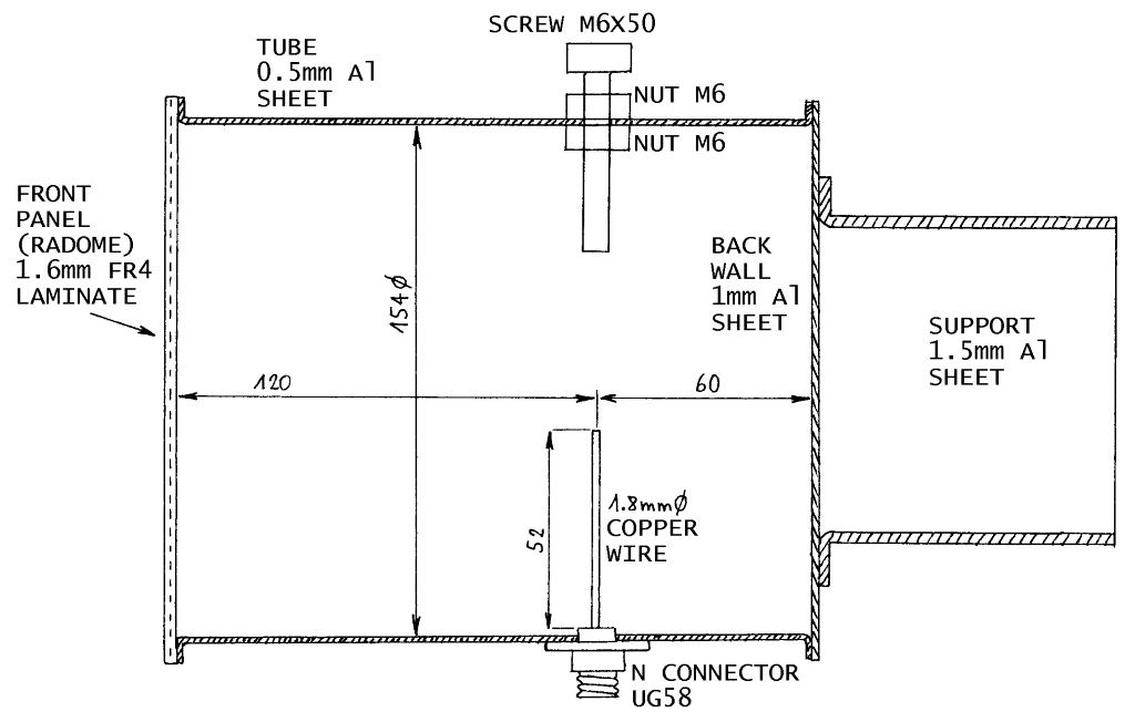
Fig.2.2.1 - Practical horn for 23cm.
The radiating aperture is covered by a disc of FR4 laminate (with any copper plating removed!) or thin plexi-glass that acts as a radome. The position of the tuning screw and the length of the feed probe correspond to the given design including all dimensions and the effect of the radome. If the waveguide section is made longer, the position of the tuning screw and the length of the probe will necessarily change!
If only simple tools are available, then it makes sense to build the individual components of the horn from aluminum sheet and bolt them together with small M3X4 or M3X5 screws. Aluminum is a good electrical conductor providing low losses in the antenna structure and does not require any special environmental protection. The required mechanical components for the horn for 23cm are shown on the following drawing:
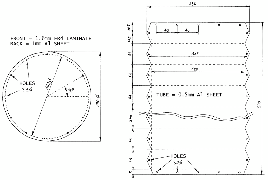
Fig.2.2.2 - Mechanical components of the horn for 23cm.
The antenna is first assembled together using just bolts, making all necessary adjustments like feed-probe length and tuning-screw position. Afterwards the antenna is disassembled so that all seams can be sealed with small amounts of silicone sealant. Finally, do not forget a venting hole or unsealed seam in the bottom part of the antenna, where any (condensation) moisture can find its way out of the antenna!
The measured E-plane and H-plane radiation patterns of the prototype antenna are shown on the following plots:
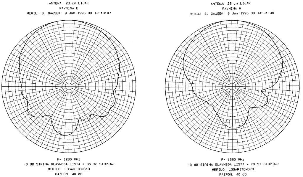
Fig.2.2.3 - E-plane and H-plane radiation patterns of the horn for 23cm.
The measured patterns in both planes at a number of different frequencies were used to compute the directivity as shown on the following plot:
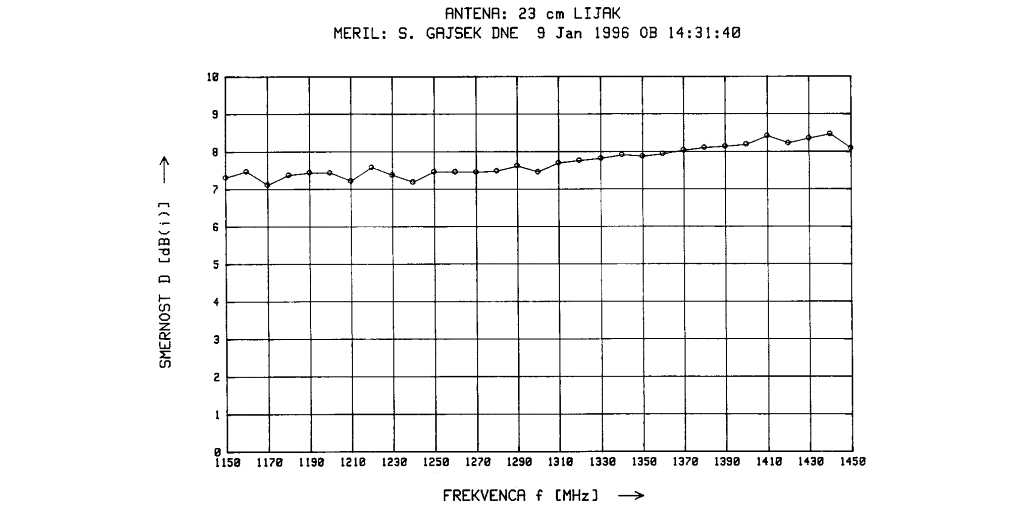
Fig.2.2.4 - Directivity of the horn for 23cm.
The operation of a simple waveguide horn is disrupted when higher-order modes are excited. In the case of a simple feed probe in a circular waveguide, the first disturbing mode is already the TM01 mode. The latter causes an unsymmetrical illumination of the aperture resulting in a squint of the direction of radiation.
The appearance of higher-order waveguide modes means that not every coffe can makes a useful antenna for the desired frequency range! The prototype horn for 23cm displays a large squint of the main lobe due to higher-order modes already at 1450MHz as shown on the following plot:
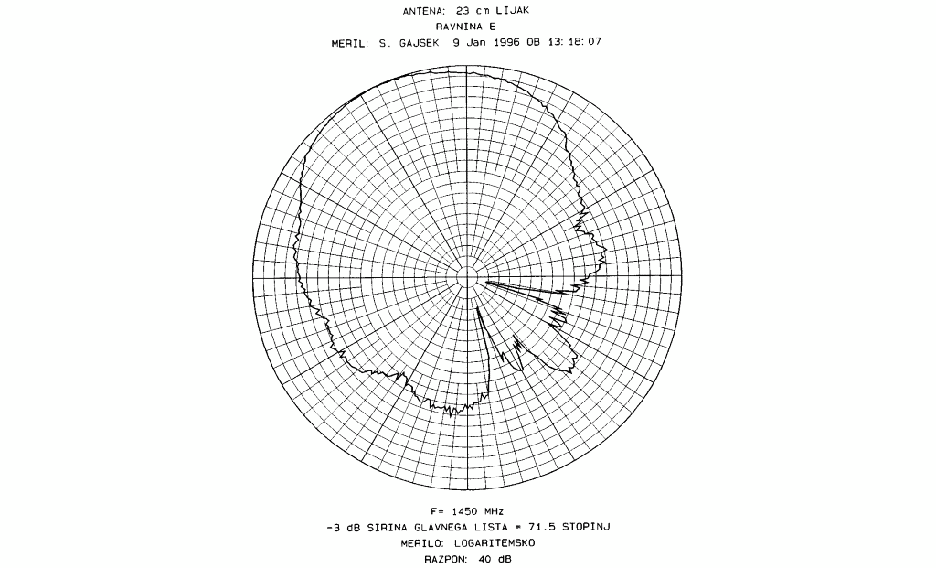
Fig.2.2.5 - Main-lobe squint due to higher-order modes.