(THEORY)
(DESIGN)
(MODULES)
(ASSEMBLY)
(OPERATION)
(ARM DSP)
(HOME)
Vertical Navigation Radar
Matjaz Vidmar, S53MV
4. Assembly
The assembly of the vertical navigation radar should start with the most critical microwave modules, described in the previous section "Modules". Both the transmitter and receiver microwave sections are built as microstrip circuits on double-sided teflon laminate with a dielectric constant of 2.43 and 19mils (0.5mm) thickness. The top side is shown on the following illustration while the bottom side is not etched to act as a ground plane:
The two microwave modules are soldered into a frame made from 0.3mm thick brass sheet. The frame includes mounting lugs and holes for feed-through capacitors as well as coaxial cables, as shown on the following drawing:
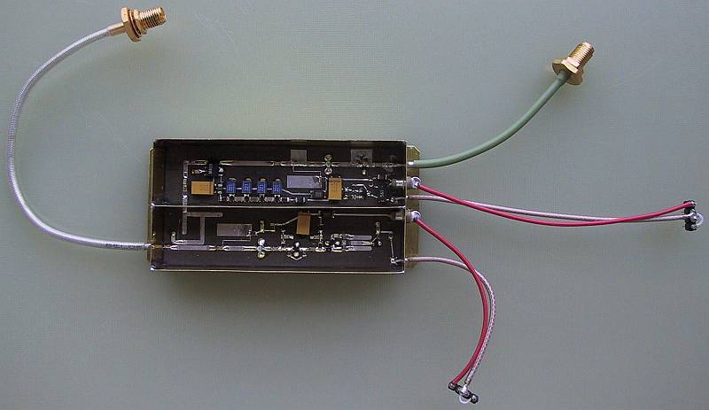
Finally, the assembled RF front end is equipped with cables and connectors. All coaxial cables have teflon insulation so that their shielding can be soldered directly to the brass frame. All supply connections go through feed-through capacitor, as shown on the following image:
The remaining four modules are built on four conventional, single-sided printed circuit boards, etched on 0.8mm-thick FR4 laminate. All SMD components are installed on the bottom side while components with wire leads are installed on the top side. The circuit board patterns are shown on the following illustration:
The original PCB files, PIC software and voice recording are available in the following archive:
PCB files, PIC software & voice

The completed modules are installed in an aluminum case. The latter includes a central frame and backplate made from 1mm-thick aluminum sheet, top and bottom covers made from 0.6mm-thick aluminum sheet and a front plate made from 2.5mm-thick plexiglass. The size of the box is selected to fit the dimensions of the graphical LCD module. The individual case components are shown on the following drawing:
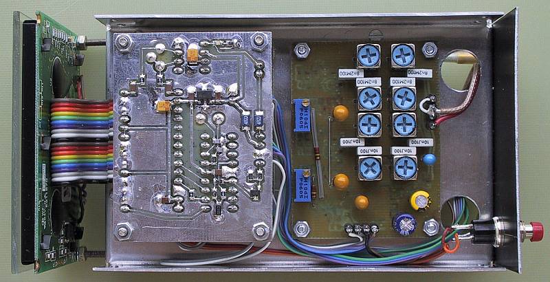
The sweep module and the microwave front-end are installed on the bottom side as shown on the following image:
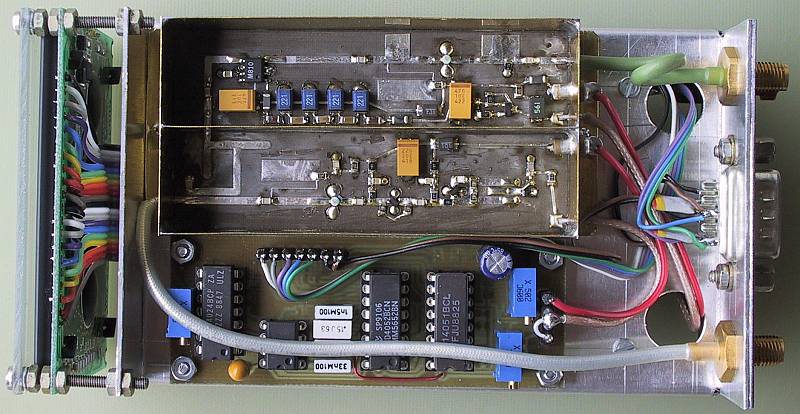
All connectors are also installed on the bottom side and hold together the frame and the backplate, as shown on the following illustration:
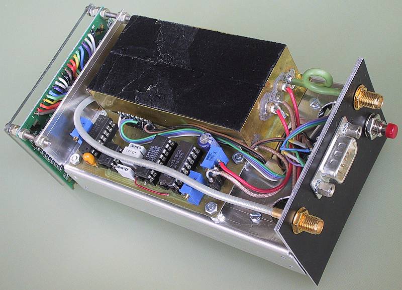
Finally, microwave absorber foam is installed on top of both microwave modules. No further shielding is required for the microwave front-end. The microwave absorber suppresses unwanted resonances and thus improves the linearity of the VCO, which in turn improves the resolution of the radar. The installation of 1cm-thick absorber foam is shown on the following image:
Two female SMA connectors are used for the receive and transmit antennas. The power supply and the audio output go to a male DB9 connector. Two 470pF capacitors are installed on this connector to block interference from other radio transmitters (in particular the VHF two-way radio) on-board the aircraft. The pin assignments of the DB9 connector are shown on the following drawing:
The nominal supply voltage is 12V to 14V DC, negative grounded. The current drain of the complete instrument is around 260mA, including the LCD backlight but with the voice synthesizer inactive. The power drain stays below 300mA when the voice synthesizer drives a high-impedance load (like an intercom). It can grow up to 500mA and beyond when driving a low-impedance loudspeaker.
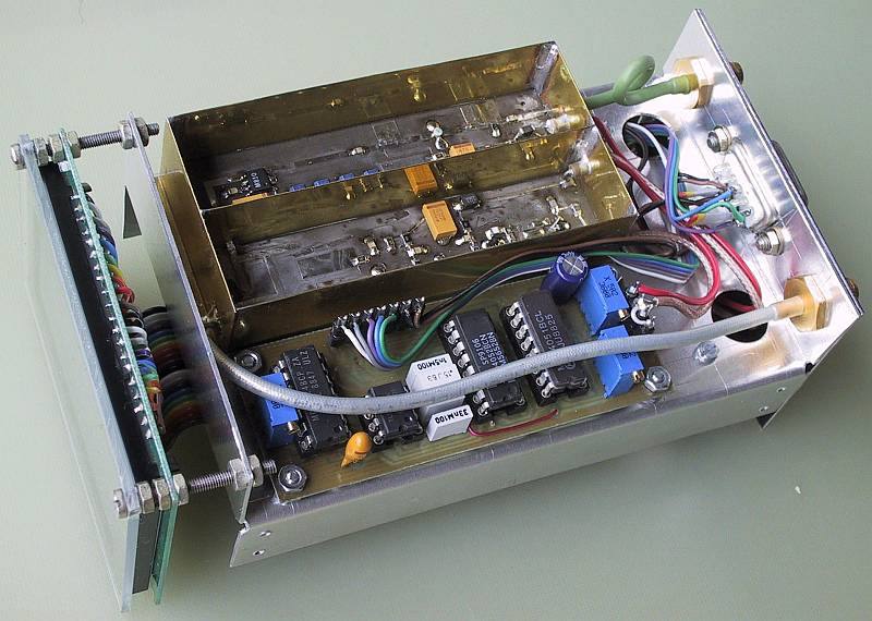
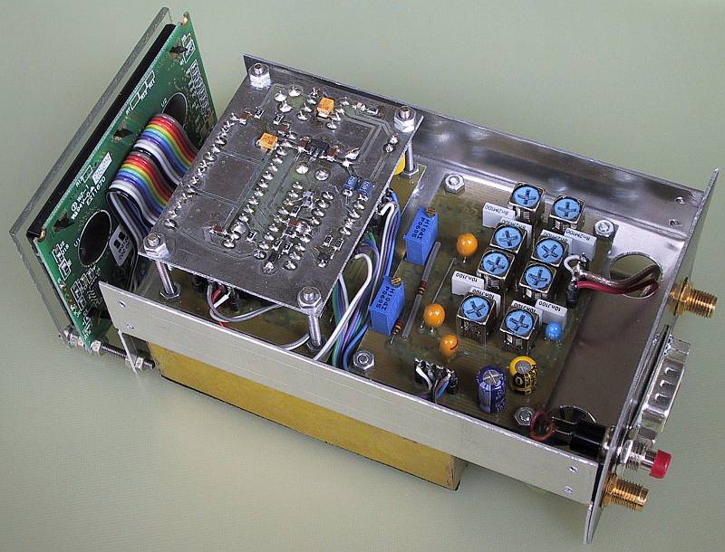
The remaining three modules: the IF module, the main processor and the voice synthesizer are installed on the top side, as shown on the following image:
The voice synthesizer is installed on top of the CPU module using four long M2.5 screws. Two additional long M2.5 screws are used to hold the front plate and LCD module, as shown on the following image:
The complete instrument installed in the described aluminum case weights around 335grams. A pair of 4.3GHz antennas as described in the following text weights 135grams. Two antenna cables, supply and audio wiring weight another 250grams. The total weight of the installed instrument is therefore around 720grams.
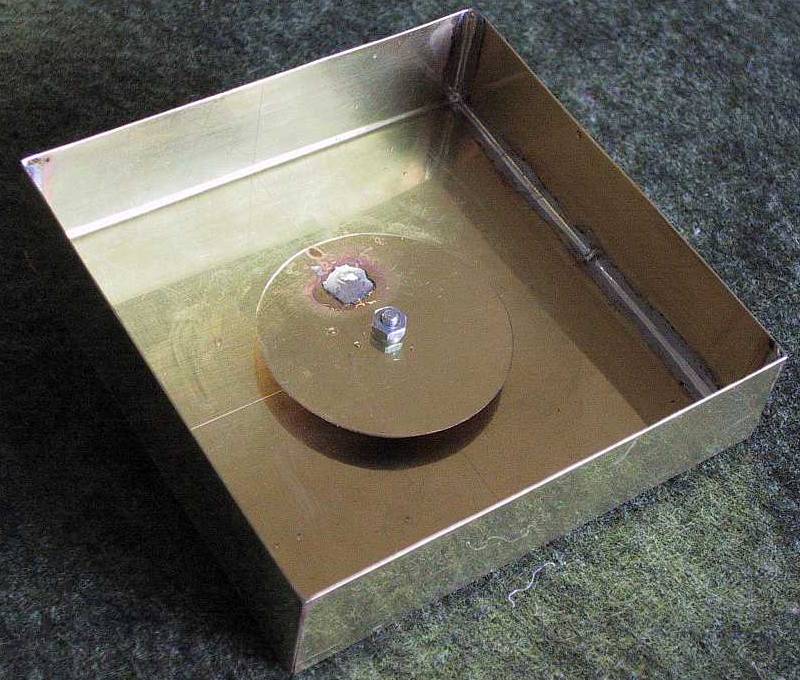
The described vertical navigation radar can be used with a pair of standard, linearly-polarized radio-altimeter antennas. A practical antenna for 4.3GHz with the required radiation pattern and good radiation efficiency is a circular patch inside a square cavity. The components of this antenna are shown on the following drawing:
The patch is held in place by a M2.5 screw while the spacing from the cavity is defined by two M2.5 nuts. The gold-plated flange of a female SMA connector is soldered from the outside while the central conductor goes through the 5mm diameter hole in the cavity and is soldered into the 1.5mm hole in the patch. One completed antenna is shown on the following image:
Two such antennas have to be installed on-board the aircraft at a sufficient spacing. The recommended spacing is around 60cm (2feet). An example of antenna installation on-board a Pipistrel Sinus motorglider (standard tailwheel version) is shown on the following drawing:
Since the bottom fuselage of the motorglider is made of glass-fiber composites that are transparent to microwaves, the antennas are conveniently installed inside between the fuselage bottom and cockpit floor. Both antennas must be oriented in the same way to achieve the same polarization. Please note the recommended antenna orientation: position of the SMA connectors, on the above drawing.
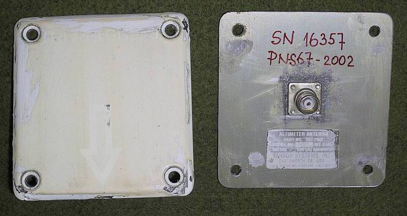
Standard, commercial radio-altimeter patch antennas can be used on aircraft with conducting fuselages: carbon-fiber composites or aluminum sheet. Two such antennas, equipped with female TNC connectors, are shown on the following image:
The two antennas can be installed either along the transversal (pitch) axis of the aircraft, as in the above example or along the longitudinal (roll) axis of the aircraft, as usual on large airliners. In both cases it is important that the polarization is selected so that the electric field vector is at right angle with respect to the installation axis of the antennas. Selecting TE (transversal-electric) polarization is necessary for two reasons:
(1) The reflection from ground is higher for TE waves than for TM (transversal-magnetic) waves due to the Brewster effect. This is especially important at very low altitudes during the landing flare.
(2) The conducting surface of the fuselage provides a high attenuation for TE waves therefore minimizing the crosstalk between the two antennas. On the other hand, a conducting surface may even improve the propagation of TM waves.
Depending on the height of the aircraft landing gear, the cable lengths to the two antennas may need adjustments to calibrate the radar at low altitudes. The alignment and testing of the whole vertical-navigation-radar installation is described in the last section of this article "Operation".
(THEORY) (DESIGN) (MODULES) (ASSEMBLY) (OPERATION) (ARM DSP) (HOME)