1. Firmware
Back in the times of AX.25, the TNC or network-node firmware was usually programmed into an EPROM. This required a specialized EPROM programmer, usually connected as a peripheral to the 8-bit home computer. Some specialized software was required to use each particular programmer.
The firmware was distributed in many different ways: as a source code yet to be compiled, as a hexadecimal image of the EPROM content and frequently as a programmed, ready to use EPROM device to be plugged into a socket on the printed-circuit board. Worst of all, besides the firmware some parameters had to be adjusted and then stored in the EPROM, requiring difficult firmware modification or even recompilation, frequent EPROM erasure and reprogramming.
In the 21st century, the semiconductor industry imposed a different approach to firmware programming. Complex system-on-a-chip devices are all available in SMD packages with large numbers of pins. Sockets for such devices are unreliable and prohibitively expensive if available at all. Stand-alone EPROM devices were replaced by an on-chip FLASH memory. Although a FLASH memory is much simpler to erase than an EPROM, it still requires a much more complex programming procedure than a static RAM.
All modern devices support In-System Programming (ISP) as a standard feature. Blank (unprogrammed) devices are first soldered into the final circuit board and then programmed using some dedicated pins. A very loose standard called JTAG was modified by individual device manufacturers to fit the needs of their particular devices.
Microprocessor-based devices also include In-Application Programming (IAP): the application running on the microprocessor can modify the content of the FLASH located on the same chip. Program parameters are stored in FLASH and can be simply adjusted by the firmware. The running firmware may include loading new firmware versions as well.
The *ATNC family includes several different devices with programmable FLASH memory. The NXP (Philips) LPC2xxx microcontrollers include 512kbytes of FLASH program memory to store both the firmware (ISP) and several operating parameters (IAP). The Altera MAX3000A family of Complex Programmable-Logic Devices (CPLD) include their own FLASH memory to store their logic configuration (ISP), equivalent to an electrical circuit diagram.
The NXP (Philips) LPC2xxx microcontrollers contain a 32-bit ARM7 microprocessor. The ATNC firmware is written in 32-bit ARM assembler. The ARM assembler source code uses the extension ".s" and is written using a conventional text editor like "Windows Notepad".
Three different programs are required for the firmware compilation. First, "ARMASM" will actually compile the program into an object version with the extension ".o". Second, one ore more object files have to be linked with "ARMLINK" into an ELF binary machine code with the extension ".axf". Since the latter is usually not supported by FLASH programmers, "FROMELF" may be used convert the result to more standard formats like INTEL-HEX (extension ".hex").
Hopefully, the final user will never have to perform the above procedure, either with the stand alone compilers nor with the compilers built in an even more complex programming tool ("Keil" etc). The main idea of NBP is to keep everything simple including the firmware. Firmware updates are not planned. All firmware parameters can be adjusted from the running firmware through IAP.
On the other hand, the final user will have to program the ARM machine code in INTEL-HEX format into the FLASH of the actual microcontroller chip. FLASH programming of the LPC2xxx family always goes through the built-in "bootloader" software. The latter allows the chip manufacturer NXP (Philips) to improve the FLASH technology while keeping the user interface unchanged!
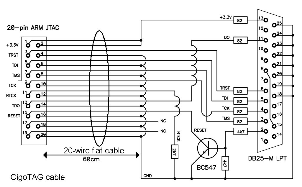
The LPC2xxx "bootloader" FLASH programming can be performed in two different ways: through the JTAG port and through UART0. The program "H-JTAG V0.9.2" only requires a simple cable called "CigoTAG" ("Wiggler" compatible) from the PC LPT port (must be a real LPT port, USB/LPT cables do NOT work!) to the JTAG port of the (x)ATNC:
Programming the ATNC/MATNC with a commercial USB JTAG, a pull-down resistor may be required on RTCK to enable the JTAG inside the LPC2138 (LPC2148). After programming with a JTAG cable, the JTAG connector on the (x)ATNC is used for different jumpers. The ATNC/MATNC use a jumper on pins (TRST) 3-4 to enable UART0 control of the ATNC/MATNC (short) or save one memory block (open). The AATNC/EATNC/RATNC/SATNC use a jumper on pins 11-12 (RTCK) to specify the smaller memory of LPC2368 or LPC2378 (short) or larger memory of LPC2387 or LPC2388 (open).
All *ATNC versions use a jumper on the unused JTAG pins 19-20 to invoke (short) the "bootloader" on UART0. In this case firmware programming is performed by the "FlashMagic" software connected through any PC COM port (may be USB/COM) to UART0 of the *ATNC. I recommend "FlashMagic" for the final user while "H-JTAG" is better suited for firmware development. In particular, I used "FlashMagic Version 5.50.1860" on most occasions.
Programmable logic uses less standard JTAG versions. Different manufacturers use different FLASH programming protocols that are only supported by their own programming tools. Altera MAX3000A devices can be programmed both by the old "MAX+plus II" software as well as with the new "Quartus".
The Altera devices used in the *ATNC family and BPSK transceiver family were all initially programmed with the "MAX+plus II 10.2 BASELINE" software. The actual circuit diagram is stored in the ".gdf" design file (binary) while the device selection, pin assignments and various options are specified in the ".acf" file (open ASCII text). Several other files are generated by the programming tool, but the most important is the ".pof" file containing binary information to be programmed in the FLASH of the EPM3032ATC44 or EPM3064ATC44 CPLD.
The ".gdf" design file is fully compatible with new software from Altera and was ported successfully to the new "Quartus II 11.1sp1 Web Edition (32-Bit)", but the device selection, pin assignments and option selection had to be done once again from "Quartus". The final result is again the ".pof" binary file. Altera also provides a stand-alone programmer for the ".pof" design files.
The Altera programming tools support different JTAG programmers. The simplest are the LPT/JTAG cables "ByteBlaster" and "ByteBlasterMV" (Multi Voltage). A functional equivalent to both original Altera cables is the simple "CigoPLD" that works with both the "MAX+plus II 10.2 BASELINE" and the "Quartus II 11.1sp1 Web Edition (32-Bit)" on real LPT ports (USB/LPT cables do NOT work):
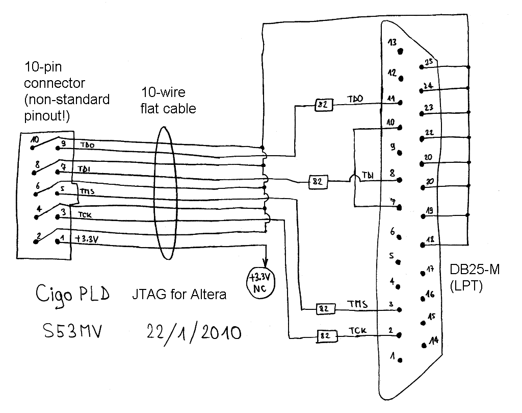
WARNING! CigoPLD uses a different signal allocation on the same 10-pin connector as original Altera cables. This was done on purpose to allow longer cable lengths with additional wires providing shielding among different signals. Both the CigoTAG and CigoPLD work with flat cables of 2m or more, although 60cm is the recommended length. The general rule with LPT cables is to avoid using additional buffers (74HC125 or 74HC244) that generate interference with longer cables. The standard LPT-port damping networks and a few additional damping resistors do the best job! If a commercial USB CPLD programmer is used, an adapter between the Altera pin allocation and the CigoPLD pin allocation is necessary!
A successful firmware programming of the microcontroller and/or CPLD already includes most of the troubleshooting in a system-on-a-chip design. In order for the programming to work, all supply voltages must be present, all clocks must be present, the reset circuitry must work etc. All of them may be checked with simple instruments.
2. Control
Control of the ATNC/AATNC/EATNC/MATNC/RATNC/SATNC could be established in several ways. AX.25 equipment like the "KISS/SLIP TNC" or the "10Mbps TNC" was controlled with simple AX.25 UI frames sent through the KISS interface, but working AX.25 terminal software is no longer available today. A Telnet or HTTP interface like in commercial WLAN (WiFi) equipment requires several protocol variables to be set to some default values, like the Ethernet MAC address, the IP4 default address and all timing parameters of the complex TCP/IP protocol.
In order to keep NBP hardware as simple as possible, a simple 9600bps, 8bits, no parity asynchronous communication is used for the control of the *ATNC in plain-text ASCII. Besides "FlashMagic", UART0 is dedicated to this control communication. In the ATNC/MATNC this communication has to be enabled by a jumper (short) between pins 3-4 of the JTAG connector.
The *ATNC accepts commands as ASCII strings terminated with a (CR) or any other control character except (BS). Only the lower 7 bits are decoded, the MSB is stripped away. Strings can be edited with (BS) or (DEL) both acting in the same way, deleting the last character in the buffer (if any) and replying (BS)+(space)+(BS) to the ASCII terminal.
The *ATNC replies include one or more ASCII strings. Each string should not contain any control characters except being terminated with (CR)+(LF). The ASCII replies are stored in a circular buffer of less than 2kbytes. In the case of too many and/or too long replies, entire sections of text may be removed while the message is truncated at arbitrary points.
At power-on, the *ATNC will present itself with an ASCII string including the hardware type (SATNC), software date (14.07.2019), processor ID (1800FF35=LPC2388) and Ethernet ID (0008872=KSZ8851SNL):
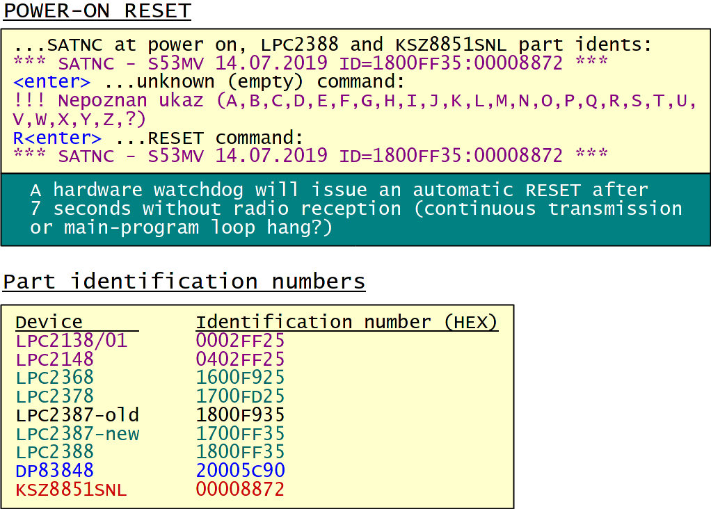
Commands are simply entered as ASCII text. Upper or lower case does not matter as long as the string is not forwarded somewhere else in converse mode or stored as text with the command "J". An empty string is an unknown command! The command "R" is similar to a power-on reset.
An on-line list of all available commands is available with the command "?". The list is different for the ATNC, AATNC, EATNC, MATNC, RATNC or SATNC. The example below shows the SATNC reply:

Of course commands also depend on the firmware version. The following description corresponds the latest (2021) firmware:
ATNC/AATNC/EATNC/MATNC/RATNC/SATNC firmware

In the following presentation the *ATNC commands will be briefly explained in a logical order. Not all commands may be present in different versions of *ATNCs. Some settings may not have any effect in some particular operating mode while they are critical in other modes.
Many commands may include one or more parameters. Only the parameters typed after the command letter will be modified. If no valid parameter follows the command letter, the parameters actually stored in RAM will be displayed.
All *ATNC settings are stored in FLASH as an 1kbyte large block starting at address 0x7B000. Rather than typing individual parameters by hand, the settings block can simply be cloned using "FlashMagic" or "H-JTAG". Care should be taken that the settings block is always cloned between identical devices only, like ATNC-ATNC, AATNC-AATNC, EATNC-EATNC, MATNC-MATNC, RATNC-RATNC or SATNC-SATNC running an identical version of firmware! Finally, do not forget that each *ATNC requires its own, usually different NBP address as well as its own, necessarily different Ethernet MAC address...
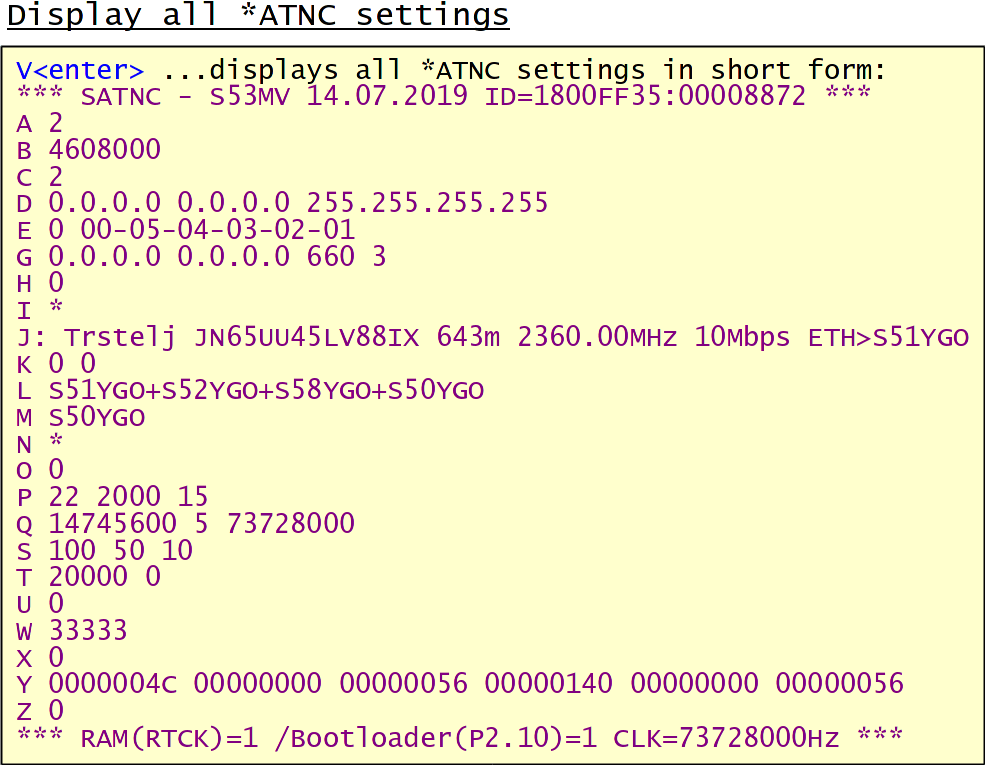
All of the *ATNC settings are visible immediately in short form with the command "V" except the detailed content of the NBP routing table "A" and the remote-command HEX password:
3. Timing
The transmission timing parameters (commands "S" and "T") are required when the *ATNC is connected to a radio transmitter:
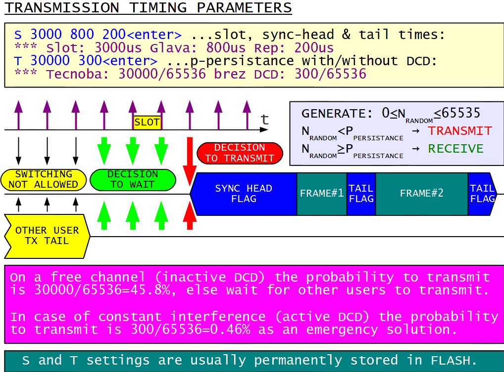
Slot time, sync-head time and tail time are all specified in microseconds. Some slow radios (old 13cm BPSK transceiver) may require a longer sync-head time. The tail time is required to flush all FIFOs in the *ATNC and transmit at least one final HDLC flag. Typical "S" settings are:
S 100 50 10 ...RATNC/SATNC connected to a 10Mbps BPSK transceiver,
S 1000 250 80 ...ATNC/AATNC/EATNC connected to a 2Mbps BPSK transceiver,
S 1500 300 120 ...ATNC/AATNC/EATNC connected to a 1.2288Mbps BPSK transceiver,
S 3000 800 200 ...ATNC/AATNC/EATNC connected to an old/slow 1.2288Mbps BPSK transceiver,
S 50000 10000 1000 ...MATNC connected to a 38400bps WBFM transceiver,
S 300000 200000 50000 ...MATNC connected to a 1200bps NBFM transceiver.
Two different values are specified for the p-persistance with the command "T". The first value is the conventional p-persistance waiting for an inactive DCD. The second, much lower value, ignores the DCD to allow some degraded communication even in the case of continuous interference. The second value can be set to zero to improve the transfer rate and link efficiency in the case interference is not expected. Both numbers are divided by 65536 to obtain the probability to transmit.
The NBP retry parameters (command "P") are only used with NBP over radio. They have no effect in the KISS mode nor in the "inverse" HDLC-KISS mode (MATNC). In addition to the maximum number of retries Nmax and retry time constant Tretry, the MINBLOK congestion-control parameter is also specified in the same command:
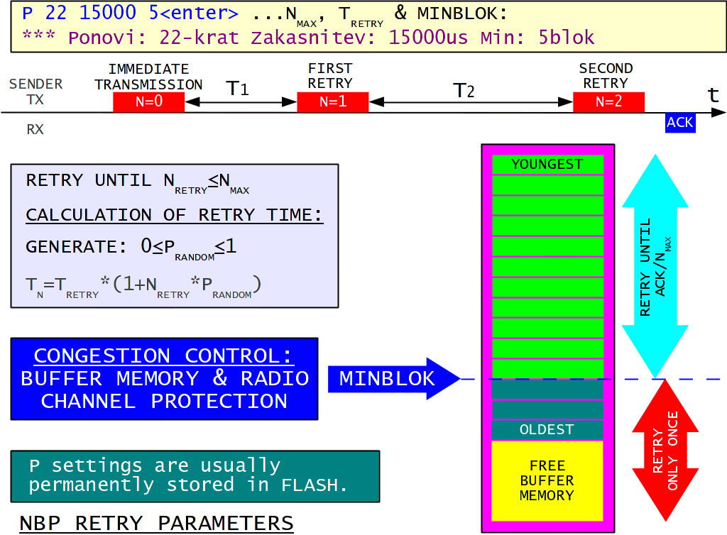
Nmax=22 is ok for all links except for very slow MATNC operation, where the MATNC may run out of memory and a smaller Nmax is recommended.
The following Tretry is recommended:
1500us for short (10km) 10Mbps links,
2000us for long (70km) 10Mbps links (propagation delay!),
10000us for 2Mbps links,
15000us for 1.2288Mbps links,
330000us for 38400bps links,
1000000us for 1200bps links with short frames (APRS).
MINBLOK=5 is appropriate for an ATNC or MATNC with 15 available memory blocks or an EATNC with a LPC2368 and 20 available memory blocks. For an EATNC or SATNC with a LPC2387 and 45 available memory blocks a higher MINBLOK=15 is recommended. MINBLOK=30 may make sense in an AATNC with a LPC2387 and 55 available memory blocks to avoid blocking the local loop with large amounts of data.
4. Addressing
In order to use NBP, several addresses need to be set up:
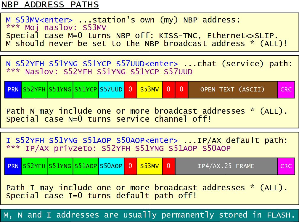
All addresses are usually represented in the modulo (36) format as strings of (upper case) letters and numbers. Amateur-radio callsigns can be used as NBP addresses. The most important setting is the station's own (my) address with the command "M". This setting turns on NBP in an *ATNC.
Two separate paths are specified for the service channel (command "N") and as a default path for IP4 or AX.25 frames (command "I"). Address paths may have up to 16 individual addresses. The last address is the final destination while all other addresses specify the network nodes where the data frames are going to travel. The service channel and/or the default path may be turned off by inserting zero in their address paths.
The operation of an ASV local wire loop is specified by the command "L":
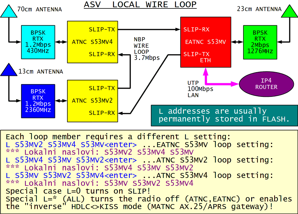
Frames addressed to destinations in the "L" list will be sent to the local wire loop, while all other frames will be sent to the radio link. A frame sent to a broadcast "*" destination will be sent both to the radio link and to the wire loop. Inserting zero in the "L" list switches UART1 to SLIP mode.
An EATNC/SATNC operating solo may require at least one nonzero entry in the "L" list to turn off SLIP and enable the Ethernet port. This single entry may be the station's own address. In this case "M" and "L" settings are identical.
Inserting the broadcast address "*" in "L" effectively disables NBP on the radio link, since all frames are sent to the local wire loop. An "*" in the first place (or solo) in the "L" list completely disables the radio HDLC interface in the ATNC/EATNC to save CPU power.
The setting L=* may not make any sense in an ATNC/AATNC/RATNC. The settings M=0 and L=* disables both NBP and the radio link, switching an EATNC into an Ethernet-SLIP converter. Finally, the setting L=* invokes the "inverse" HDLC-SLIP mode of a MATNC.
The ASV node skip is further controlled by the order in which the individual addresses are entered in the "L" list. Besides their own NBP address, all *ATNCs also process the data frames addressed to destinations from their own "L" list. Then the sending *ATNC#A finds the distance to the destination *ATNC#B in the local wire loop by looking at its own "L" list. For example, a destination two (2) hops away must be entered in the second (2) position in the "L" list! Every member of a local wire loop therefore requires a different, carefully compiled list "L" to reach the correct destination in the ASV node-skip mode.
Besides the default path, the ATNC/AATNC/EATNC/MATNC/RATNC/SATNC is able to perform different routing for up to 10 particular IP4 addresses or up to 10 particular AX.25 callsigns. The operation of this additional NBP routing table is controlled by the command "A":
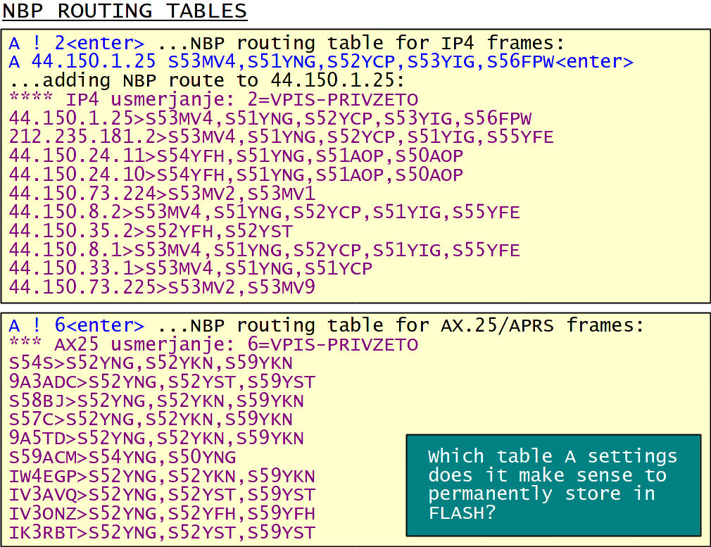
The operating mode of the NBP routing table is selected by:
A ! 0(enter) ...IP4 routing off,
A ! 1(enter) ...IP4 routing read only,
A ! 2(enter) ...IP4 routing auto update without default path,
A ! 3(enter) ...IP4 routing always auto update,
A ! 4(enter) ...AX.25 routing off,
A ! 5(enter) ...AX.25 routing read only,
A ! 6(enter) ...AX.25 routing auto update without default path,
A ! 7(enter) ...AX.25 routing always auto update.
Routes can also be added manually with the command:
A (IP4/AX.25 destination) (NBP path)(enter) ...add new route or modify existing route.
Routes can be removed by omitting the NBP path in the above command.
In an unattended station (gateway, server, IP camera etc) it makes sense to keep the FLASH table "A" empty and the auto update on (modes A!2 or A!6) without default path. The table "A" will grow automatically as traffic comes in.
In a home or office station with human-operator presence it makes sense to store additional routes to known destinations (servers, IP cameras, AX.25 callsigns etc) in FLASH. Auto update may be either off (modes A!1 or A!5) or on (modes A!2 or A!6) without the default path.
Always-auto-update modes A!3 and A!7 are useful to monitor all traffic. The table "A" list stored in FLASH may be kept empty in this case.
5. Telemetry and telecommand
The ATNC/AATNC/EATNC/RATNC/SATNC have two analog telemetry inputs TLM1 and TLM2 connected to a 10bit A/D converter. The latter operates in burst mode independently of the LPC2xxx ARM7 core scanning 5 inputs. Three consecutive inputs (TLM1) are dedicated for noise filtering to the RSSI voltage coming from the radio receiver. The hardware already includes a 2:1 resistive divider corresponding to a 6.6V full scale. An additional capacitor to ground can provide additional noise filtering.
The fourth input (TLM2) requires external components to measure voltages, temperatures (see examples) or other quantities. The internal resistance of the TLM2 source should be kept below 5kohm for consistent measurements. Finally the last scanned input is grounded to reset capacitors internal to the LPC2xxx ADC for consistent measurements of TLM1.
Besides showing the direct A/D output, the command "Y" allows simple data conversion. The command "Y" includes six (6) hexadecimal parameters as two groups of three parameters for each telemetry channel. The raw A/D output is always displayed regardless of the "Y" settings. The A/D output is first multiplied by the first parameter, then divided by 1024, then the second parameter (may be negative) is added and the final result is divided by 10. The display includes a decimal point before the last digit. The third parameter specifies up to four ASCII characters to display the units ("V", "C", "mA", "%", "km/h" etc). Control characters (zeros) are simply not displayed.
The telemetry and telecommand status are visible with the command "K". Two values are displayed for TLM1. "S:" is the RSSI sampled at the end (tail) of the last valid packet while "1:" is the current RSSI value (usually noise):
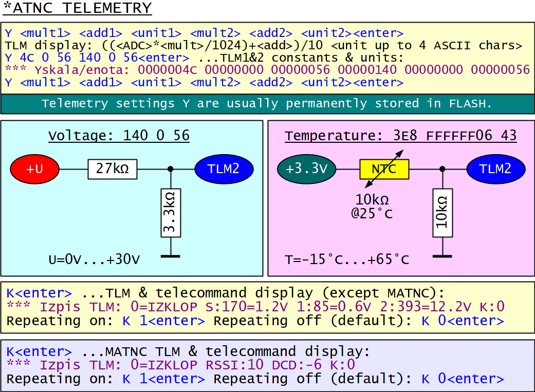
The MATNC does not have any analog telemetry inputs. Two telemetry values are obtained from the software DSP demodulator. "RSSI:" is the input signal or noise level. "DCD:" is the internal analog DCD value, negative invalid and positive valid.
In the MATNC the command "Y" is used to specify four parameters of the software DSP modem. The adjustable RX HPF may compensate the deemphasis built in FM radio receivers. The MIClevel should be adjusted to correctly modulate the transmitter. Finally the desired modem and baudrate have to be specified:

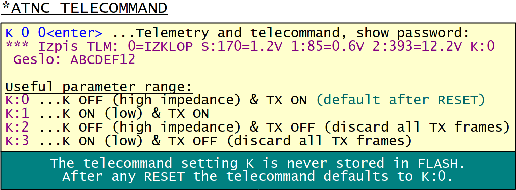
The *ATNC family includes a single telecommand output. The latter is an open-collector driver in the ATNC/AATNC/EATNC/RATNC/SATNC and a simple TTL output in the MATNC. The default state of this output after RESET is OFF (high impedance) or TTL low. It can be turned ON with either the command "K" or with the remote command "////-". Further the telecommand allows turning OFF the radio transmitter either with the command "K" or with the remote command "////-":
6. System
The command set also includes a few critical system settings:
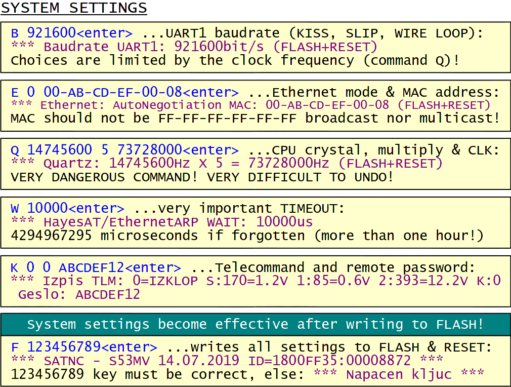
The UART1 baudrate (KISS, SLIP or local wire loop), selected with the command "B", only becomes effective after restarting the *ATNC by storing all parameters to FLASH.
The Ethernet mode (command "E" in EATNC/SATNC only) can be set 10 (10Mbps), 11 (10Mbps with MDIX), 100 (100Mbps) or 101 (100Mbps with MDIX). Any other number invokes AutoNegotiation and AutoMDIX. The latter setting (may be 0 for convenience) is usually the best choice.
The Ethernet MAC address should be set to something different form all other Ethernet LAN members. Besides the broadcast address, multicast addresses starting with an odd first byte should be avoided! Both the Ethernet mode and MAC address are written to peripheral registers, requiring a restart of the EATNC/SATNC by storing all parameters to FLASH.
The most dangerous command "Q" specifies the crystal frequency, the multiplier and the processor clock frequency. The firmware will check that the numbers are within reasonable limits, else the previuos setting or the default setting 14745600 4 58982400 is applied. The new values must be written to FLASH and the system restarted for the new values to take effect.
A wrong setting of "Q" will unlock the PLL inside the microcontroller making any further operation impossible. The only way back is to erase the whole 1kbyte FLASH parameter block starting at 0x7B000 with "FlashMagic" or "H-JTAG". An erased parameter block includes a far too high clock frequency. This will be detected as an error at the next system start and replaced with the default value (14.7456MHz crystal multiplied by 4).
A very important timeout is set by the command "W". In SLIP mode (except RATNC), it defines when to flush the SLIP-frame buffer to allow switching back to the Hayes-modem "AT" commands with the string "+++". In Ethernet mode (EATNC/SATNC only), it defines how much to wait after an ARP request. 10000 microseconds (10ms) is an acceptable value for both. The value from an erased FLASH will block the Ethernet port for more than one hour after the reply to a single ARP request is lost!
Critical remote commands are protected with a password. The latter is a 32bit number written as up to 8 HEX digits. The password is first set with the command "K" and then stored in FLASH with the command "F". The password is only shown when the command "K" is followed by at least two parameters. The third parameter, if specified, is the new password.
The complete block of parameters is written to FLASH with the command "F". The latter requires typing the key 123456789 to avoid unwanted modifications of the FLASH content. After successfully writing to FLASH, the *ATNC will reboot to refresh the registers of all affected peripherals.
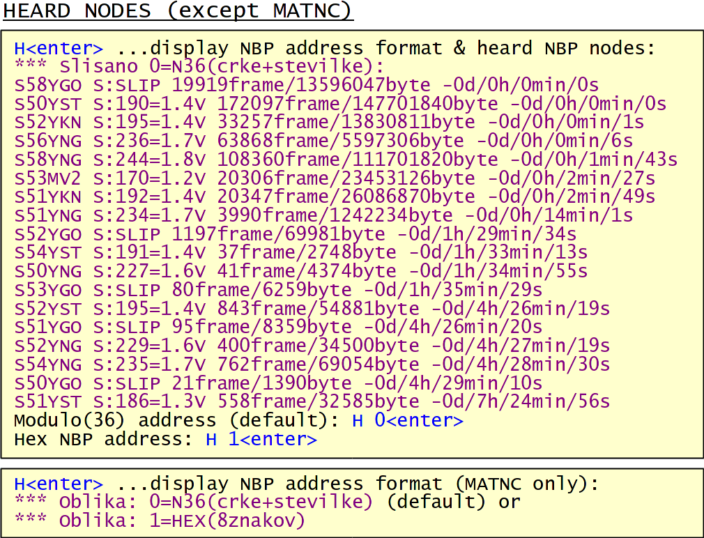
The ATNC/AATNC/EATNC/RATNC/SATNC firmware can display a list of heard NBP nodes with the command "H". Each line contains the NBP address followed by the RSSI, number of frames heard, number of bytes heard and the time delay the NBP address was heard last. The maximum number of entries depends on the available memory in a particular version of the *ATNC (unfortunately none in the MATNC). Finally the command "H" allows displaying NBP addresses both in modulo(36) format (default) or as HEX numbers (useful for testing):
The *ATNC firmware includes several commands for status monitoring:
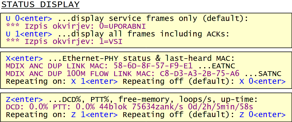
The command "U" is used to select which frames are displayed. The default setting after reset corresponds to the command "U 0": only service-channel data frames reaching the final destination will be displayed. In addition to the frame content (with any control characters stripped away), the address path will be shown in all cases.
The command "U 1" will display all frames, data and acknowledge, traveling through the *ATNC. In addition to the address path and frame content, the *ATNC port as well as the pseudo-random, lifetime or distance tag will be displayed. The RATNC/MATNC will also decode the NBPv2 acknowledges. The *ATNC port and direction is described by a single letter:
L ...frame received on the local wire loop,
R ...frame received on the radio port,
S ...frame sent to the local wire loop and
T ...frame sent to the radio port.
First, the command "U 1" is very useful to learn how NBP works. Second, the command "U 1" is useful for troubleshooting, especially when setting up the local wire loop with the command "L". Finally, the command "U 1" may be used for traffic monitoring. In this case it may be useful to switch the *ATNC to protocol-less KISS mode to listen to all traffic on the radio channel.
The command "X" displays the Ethernet-PHY status and the last-heard MAC address in an EATNC/SATNC. It is very useful to identify what is wrong with the UTP cable and how the Windows or Linux on the other end of the UTP cable crashed. A repetitive "X" display once per second may be turned on or off, the reset default is off.
Both Ethernet-PHYs, the DP83848 in the EATNC and the KSZ8851SNL in the SATNC are able to correct the polarity of a received Manchester-encoded 10Mbps Ethernet signal. Signal polarity does not matter in 100Mbps Ethernet due to differential encoding. The DP83848 signals 10Mbps operation and does not support flow control in the EATNC. The KSZ8851SNL signals 100Mbps operation, has a built-in 18kbyte FIFO and supports IEEE 802.3x flow control in the SATNC.
The command "Z" displays the status of the *ATNC: the DCD%, the PTT%, the number of free-memory blocks, the number of loops-per-second (free CPU capacity) and the *ATNC up-time (days/hours/minutes/seconds). A repetitive "Z" display once per second may be turned on or off, the reset default is off.
7. Ethernet
Ethernet is a protocol that may transfer different payloads on the same physical channel. Ethernet frames include their own Ethernet-MAC addresses, a type field specifying the payload, the payload itself and a 32-bit CRC:
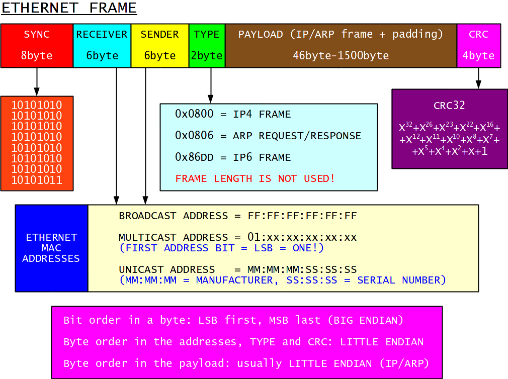
All Ethernet hardware generates/looks for the standardized 8-byte SYNC at frame start and automatically generates/checks the 4-byte CRC at frame end. An Ethernet frame may include additional framing (start, stop, sync, idle) depending on the particular physical channel used.
The 48-bit Ethernet addresses are supposed to be assigned by the equipment manufacturer. Each individual product should have its own, globally unique "unicast" address. Everyone is supposed to listen to the broadcast address consisting of all (48) logical ones. Rather than correcting some old software bugs, "multicast" addresses were invented to make our life more difficult.
The Ethernet payload is specified in the 16-bit TYPE field. The same field could also be used for frame length, but this is usually not done except in NBPv2 radio frames. A very large number of TYPE fields are specified for different protocols. In practice, only three different TYPE fields are used: IP4, ARP and IP6.
Ethernet specifies both the minimum and maximum size of the payload. The minimum size is required by some old physical channels and may require padding small payload frames with zeros. The maximum size may be increased in the future, but the 1500 byte MTU is a world standard today, supported by all known hardware including the EATNC/SATNC.
Since Ethernet includes its own addresses, routing of higher-level protocol frames is required. Initially, Ethernet routing was performed by hand-written routing tables. The Address Resolution Protocol (ARP) was invented to automatically build and update routing tables. While ARP is a separate protocol supporting IP4, ARP is built into IP6 right from the beginning. Today most Ethernet equipment including the EATNC/SATNC supports IP4 and the corresponding ARP.
When an IP4 frame has to be sent over an Ethernet network, an ARP request for that particular IP4 destination is sent to the Ethernet broadcast address first. Hopefully, an ARP response is received in time, specifying the Ethernet-MAC address for the requested IP4 destination. The IP4 frame can now be sent to the specified unicast MAC address. The latter may be stored together with its corresponding IP4 destination in an ARP cache to limit further ARP requests for the same IP4 destination. The ARP cache is flushed after some time (usually 2...15 minutes) to keep it periodically updated.
The ARP cache might grow several orders of magnitude larger than the number of different Ethernet-MAC addresses in a local-area network. Since most IP4 destinations, in particular the external ones, are only reachable through a single Ethernet-MAC address, the latter may be considered the default gateway. IP4 frames for external destinations simply send an ARP request for the default Ethernet-MAC address or use the corresponding entry in the ARP cache:
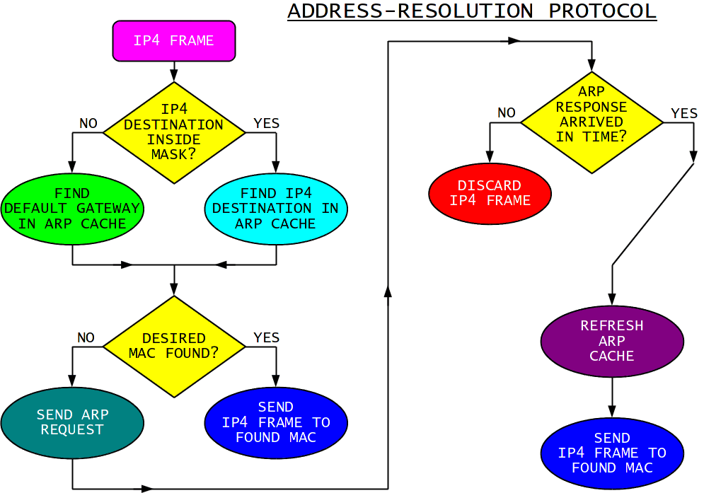
In order to separate local from external IP4 addresses in a simple way, an IP4 address domain is usually defined. Individual ARP requests are only required for IP4 destinations inside the domain mask. A single ARP request is required for all IP4 destinations outside the domain mask. In order to use the same ARP protocol in both cases, a default-gateway IP4 address is invented. The latter may not and needs not to correspond to any existing IP4 host! The only thing that matters is that some piece of equipment answers with an ARP response containing the default-gateway Ethernet-MAC address.
In order to understand the settings of an EATNC/SATNC, it is very important to understand the above description of the ARP, IP4 domain and default gateway into detail! The EATNC/SATNC is not an IP4 host. Yet the EATNC/SATNC has to perform Ethernet routing tasks that are more complicated than those found in a desktop computer or a LAN router. The IP4 domain settings of an EATNC/SATNC are therefore necessarily more complicated!
An EATNC/SATNC may be connected to a single desktop computer. An EATNC/SATNC may also be connected to an Ethernet switch supporting a LAN with many IP4 hosts like desktop computers, IP cameras etc. Two or more EATNCs/SATNCs may also be connected to an Ethernet switch supporting a LAN with many IP4 hosts. An EATNC/SATNC may be connected to an IP4 router not performing NAT. NAT (Network-Address translation or IP4 masquerade) may be turned on in an IP4 router and an EATNC/SATNC may be connected to either side of the NAT. Finally, DHCP requests (automatic IP4 address assignments) may be either handled or blocked, depending on the network configuration.
In order to fulfill all of the above requirements, the EATNC/SATNC Ethernet routing is specified by two different commands "D" and "G". The command "D" specifies the IP4 domain for the incoming traffic from the Ethernet LAN to the EATNC/SATNC. The command "G" specifies the default gateway and the ARP operation for the outgoing traffic from the EATNC/SATNC to the Ethernet LAN.
The command "D" specifies how are incoming ARP requests handled by the EATNC/SATNC. Both an accept domain and a reject subdomain are defined:
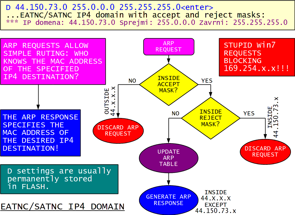
The EATNC/SATNC does not answer to ARP requests outside the accept domain. The EATNC/SATNC does not answer to ARP requests inside the reject subdomain either. The EATNC/SATNC only answers to ARP requests inside the accept domain but outside the reject subdomain. All incoming IP4 traffic to the EATNC's/SATNC's unicast address is routed to the NBP network afterward.
If two or more EATNCs/SATNCs are connected to an Ethernet switch, care should be taken that their domains do not overlap! Only a single EATNC/SATNC or another Ethernet device is allowed to answer to an arbitrary ARP request. An ARP response actually means that the corresponding EATNC/SATNC or another Ethernet device knows the path to the requested IP4 destination.
If a single WinXP/Linux computer is connected to an EATNC/SATNC, no special domain setting is required. WinXP/Linux is therefore happy with:
D 0.0.0.0 0.0.0.0 255.255.255.255(enter)
The same is not true for the stupid Win7. At least the domain 169.254.x.x needs to be blocked, else Win7 does not work.
The command "G" specifies where are EATNC/SATNC ARP requests sent in the Ethernet LAN and how are the corresponding ARP replies handled by the EATNC/SATNC. In particular, the command "G" specifies the default gateway, the mask relative to the specified gateway, the ARP cache lifetime and the ARP mode:
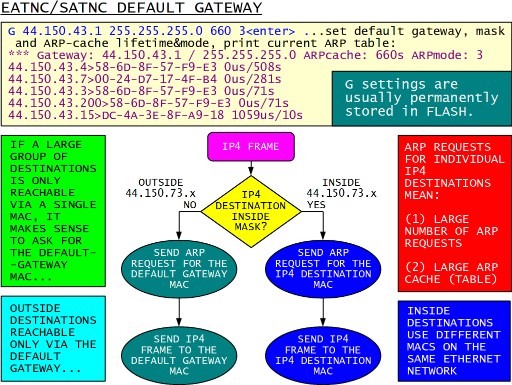
The EATNC/SATNC will send individual ARP requests for all IP4 destinations inside the mask applied to the specified default-gateway IP4 address. The EATNC/SATNC will send a single ARP request for the specified gateway for all IP4 destinations outside the specified mask.
The EATNC/SATNC automatically builds an ARP cache. The content of the latter is also shown by the command "G" and may have up to 25 entries. Each entry includes the IP4 address, the corresponding Ethernet MAC address, the ARP reply time in microseconds and the remaining cache lifetime of the entry in seconds. The initial cache lifetime is set to the specified ARP cache lifetime and then automatically decremented each second. The cache entry is removed either when overwritten with fresh data or its lifetime drops to zero.
When the EATNC/SATNC wants to transmit an IP4 frame over the Ethernet, it first looks into the ARP cache. If the corresponding destination MAC address is found in the ARP cache, the IP4 frame is simply sent there.
If the corresponding destination MAC address is NOT found in the ARP cache, an ARP request is sent on the Ethernet and any pending IP4 frames are put on hold. The EATNC/MATNC then waits the amount of time specified with the command "W". If the corresponding ARP reply is received in time, the pending IP4 frame is sent immediately to the MAC destination found and other IP4 frames are processed in the same way. If no ARP reply is received in time, the pending IP4 frame is discarded and other IP4 frames are processed in the same way.
All valid ARP replies are always included in the ARP cache. In addition other ARP information may also be included in the cache, depending on the selected ARPmode:
ARPmode:0 ...only valid ARP replies are included in the ARP cache,
ARPmode:1 ...unsolicited (delayed) ARP replies are included in the ARP cache,
ARPmode:2 ...useful ARP requests from other hosts are included in the ARP cache,
ARPmode:3 ...both unsolicited replies and requests from other hosts are included in the ARP cache.
Unsolicited (delayed) ARP replies are marked with the ARP reply time equal to the "W" setting. Useful ARP requests from other hosts are marked with the ARP reply time equal to zero. The proposed "W" setting of 10000us is always enogh for wired Ethernet networks but may not be sufficient for wireless (WiFi) networks. ARPmode:3 usually works best.
If a single desktop computer is connected to an EATNC/SATNC, there is no gateway! An ARP cache lifetime of 660 seconds (11 minutes) is always ok as well as all ARP options (3):
G 0.0.0.0 0.0.0.0 660 3(enter)
The "D" and "G" settings are completely independent! While "D" handles incoming ARP requests, "G" handles outgoing ARP requests.
The EANTC/MATNC nor the whole idea of the NBP network is NOT TO COMPETE WITH NOR TO FIGHT other technologies like IP4 routers or WLAN (WiFi) networks. The idea of NBP is to COMPLEMENT other technologies to build an even better network! A typical example of a home network with access both to the NBP network and commercial internet is shown on the following drawing:
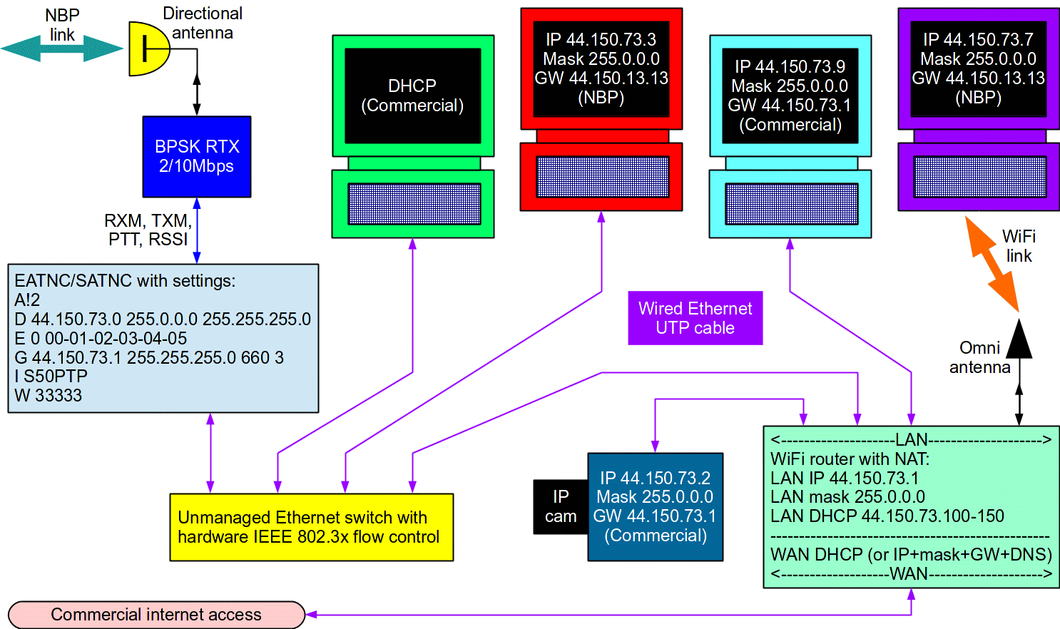
In an amateur-radio network, it makes sense to use fixed IP4 addresses from the 44.x.x.x domain. Using fixed IP4 addresses we do not need any almighty servers to find our NBP correspondents. The EATNC/SATNC accept domain is usually set to ignore DHCP requests. Conflicts with other DHCP servers that may be present in the NBP network are thus avoided. Setting the LAN domain to a subdomain of the 44.x.x.x network, for example 44.150.73.x as shown on the drawing, the following connections are possible:
(1) all LAN users can access the commercial internet by setting their default gateway to 44.150.73.1,
(2) all LAN users can access the internet (available at "I") through the NBP network by setting their default gateway to an (may be inexistent) IP outside the LAN domain, for example 44.150.13.13,
(3) all LAN users can access other individual users both on the LAN and on the NBP network according to the "I" and "A" NBP routes,
(4) all external NBP users can access any LAN users, the return NBP path being stored automatically with "A!2",
(5) all external NBP users can access the commercial internet without even knowing the local gateway IP,
(6) all external NBP users can bounce their traffic by the local router back into the NBP network according to the "I" and "A" NBP routes.
Unfortunately many inexpensive routers, IP cameras and desktop computers do not support the IEEE 802.3x flow control. The workaround is to insert a cheap unmanaged Ethernet switch between the SATNC ant the remaining LAN. Unmanaged switches usually include hardware IEEE 802.3x flow control and enough buffer memory to avoid data loss at 100Mbps Ethernet speed.
The EATNC does not support flow control. In the case of an EATNC it makes sense to force its Ethernet interface to 10Mbps, for example:
E 10 00-01-02-03-04-05(enter)
At 10Mbps Ethernet speed the EATNC/SATNC processor is usually fast enough to handle all traffic without hardware flow control. The unmanaged Ethernet switch cares about the conversion of 10Mbps to/from 100Mbps on all other ports thus avoiding slowing down the LAN.
A very simple check is to ping an IP4 station on the other side of a NBP network with very long test messages. If IP4 pings in excess of 20kbytes (but less than 64kbytes) do not make it through the NBP network and back, there may be a flow-control problem on either side of the NBP link.
8. Service
Besides setting up the operating parameters of the *ATNC, the UART0 control communication is also used for simple text chatting, remote commands and link measurement through the NBP service channel. To send information to the NBP service channel, the corresponding address path has to be set with the command "N" and the *ATNC has to be switched to the converse mode with the command "C":
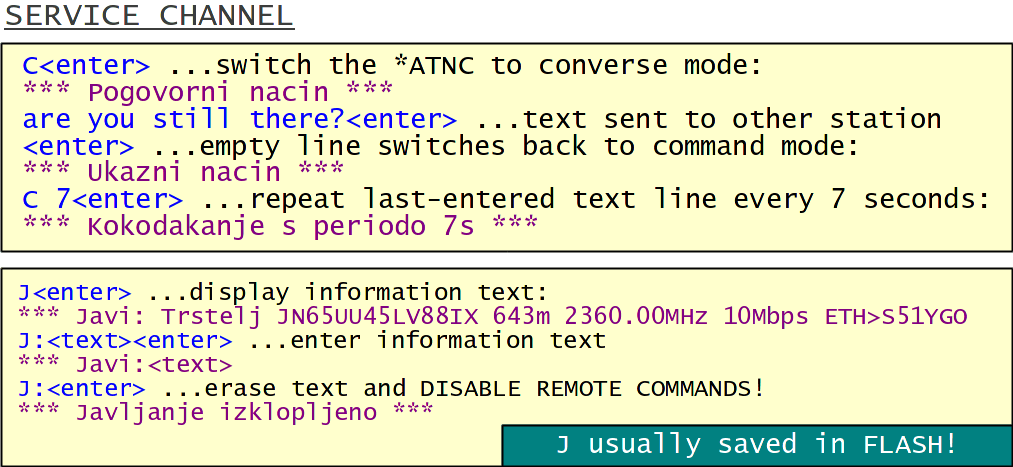
Any text typed after the command "C" will be sent to the NBP service channel. An empty line, (enter) only, will switch the *ATNC back to command mode. Any additional empty lines will be understood as unknown commands by the *ATNC. A time interval may be specified in the command "C" to repeat sending the last typed line indefinitely. This is useful to observe remote telemetry and/or to periodically issue reset commands (power cycling) to recover crashed Linux equipment (routers, IP cameras) at a remote location.
A short information text of up to 64 ASCII characters may be entered with the command "J:". This text can be read remotely with the command "////?" to get some useful information (location, frequency, bit rate, IP4 host) about the remote station. All remote commands can be disabled by erasing the information text!
Remote commands are identified by the string "////" at the beginning followed by a single ASCII character to specify the command. Remote telecommand requires adding the same hexadecimal password as entered with the command "K" into the remote *ATNC. A software reset can be issued to the remote *ATNC by sending the hexadecimal password twice.
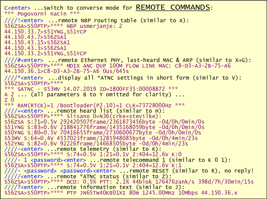
The remote telemetry "////-" reports the RSSI twice: at the end (tail) of the last valid frame (usually the remote command itself if received via radio) "S:" and after the slot time (first parameter of "S") has elapsed (usually noise without any valid signal) "1:".
During network setup and/or troubleshooting, a simple, quick and efficient link measurement is very required. The *ATNC family may perform repetitive echo measurements once per second with the command "O":
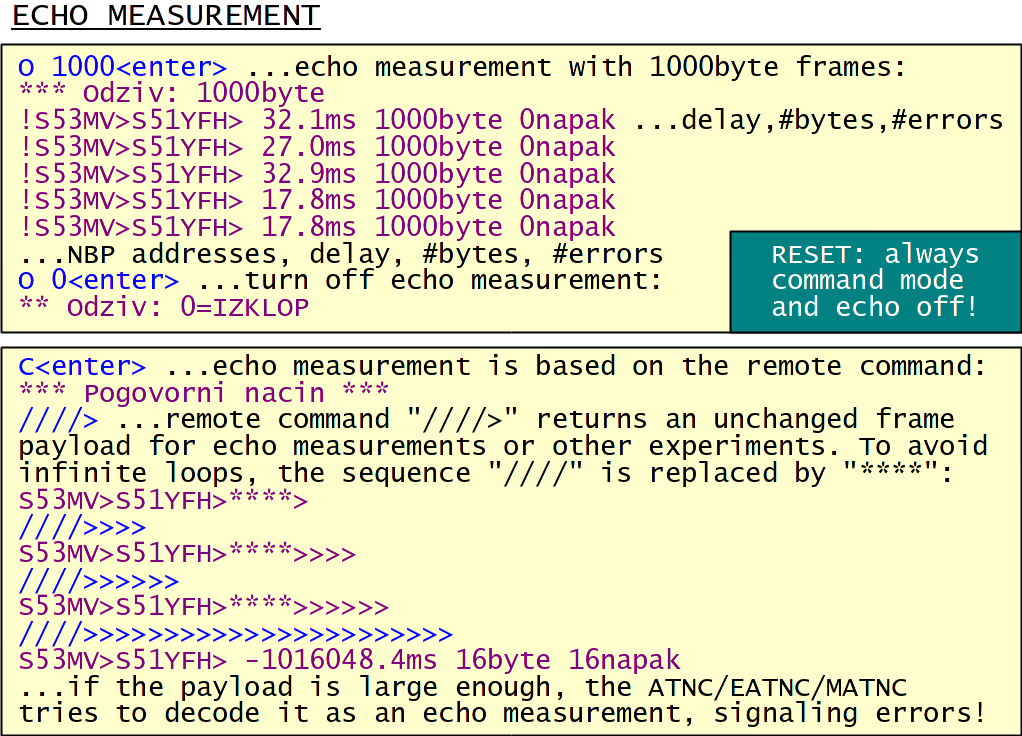
The echo-measuring data frame includes a time tag and a pseudo-random test sequence of the specified length in the command "O". The round-trip time, number of test bytes and number of error bytes found is displayed for every received reply. The time tag is also used for the pseudo-random root, so every test frame contains different test bytes. If broadcast NBP addresses "*" are specified with the command "N", a very large number of replies may be received for each interrogation.
The echo measurement is based on the remote echo command "////>". If a service-channel data frame starts with the sequence "////>" (interrogation) or "****>" (reply) and contains a sufficient number of bytes, it will be decoded as an echo measurement by any *ATNC rather than displaying its raw content.