
Simple RS232 isolator
Matjaž Vidmar, S53MV
Transferring data between two electronic devices with different power supplies is usually a problem. The two different power supplies may not have and may not even allow a common ground. The same electronic devices may generate strong electromagnetic fields and even radio-frequency fields thus interfering with the communication between two devices.
The interference problem and in particular radio-frequency interference was considered right from the beginning in Ethernet. Today Ethernet mostly uses Unshielded Twisted Pair (UTP) cables. Separation transformers are used at both link ends. Additional separation transformers may be inserted down the line. Common-mode currents are further limited by chokes to avoid unwanted radiation of radio interference. Ethernet media converters to optical fiber and back allow potential differences well over 100kV. Power-Over-Ethernet (POE) includes isolated switching power supplies. All of these solutions are efficient in a broad frequency range from mains up to radio frequency.
On the other hand, little if anything was done in USB communication. The latter was only intended for short-range communication (2m or less) with small devices. In spite of the symmetrical twisted pair, separation transformers can not be used for USB. Feeding the supply voltage along the same cable requires a common ground for both devices. USB devices are therefore rather sensitive to any kind of electrical interference. Even when no physical damage occurs, the software is usually unable to recover from interference temporary errors resulting in a "Windows blue screen of death".
On of the oldest types of computer communications is asynchronous serial RS232. The signal of the latter includes a DC component, therefore isolation transformers can not be used directly. The transmission line is not symmetrical and requires a common ground return. No supply lines are expected in a RS232 cable. Yet the RS232 communication is very popular with speeds ranging from less than 300Bit/s up to several Mbit/s over quite different cable lengths, sometimes much longer than the initial 2m. Last but not least, the RS232 is usually not directly linked to complicated higher-level protocols.
An RS232 device should withstand +/-25V on any signal line with respect to ground. Therefore RS232 devices seldom include protection circuits on outputs and/or inputs. The logical zero or "space" is defined as a voltage between -15V and -3V. The logical one or "mark" is defined as a voltage between +3V and +15V. An input voltage between -3V and +3V is undefined. Although some older RS232 receivers may require a negative input voltage for correct operation, all new RS232 receivers have an input switching threshold between +1V and +2V thus accepting TTL input signal levels. The output logical levels of most recent RS232 transmitters are -6V and +6V.
When two devices can not share a common ground, several different devices are available for signal isolation, ranging from simple optocouplers to isolation transformers with suitable electronics for signal transfer from DC up to several Mbit/s. A signal isolation may provide additional protection even when the ground potentials of two devices are close. The most common solution is an optocoupler where an infrared LED excites a phototransistor on the other side. Such a linear optocoupler is described by its current-transfer ratio ranging from 20% (old devices) up to 300%. The current-transfer ratio of darlington optocouplers usually exceeds 1000%. Darlington optocouplers are usually too slow for useful data transmission but there are other more complicated solutions for higher data speeds.
If TTL signal levels are only required, an optocoupler isolation may be very simple:
Standard RS232 does not provide any supply voltage in any direction. Please remember that GND side A has to be kept isolated from GND side B! Therefore two separate, isolated power supplies are required for sides A and B respectively. Furtunately a standard RS232 output is able to drive an optocoupler LED directly without additional power supply. On the other side, a power supply is required for the optocoupler receiver with a phototransistor.
Since no power supply is available at either side of a RS232 link, one or more handshake RS232 signal outputs can be used as power sources. RTS is usually available on both sides of the RS232 link. If unused it has to be connected to the CTS input of the corresponding side, therefore linking pins 7 and 8 of the DB9 connector. The same signal can be used as a +6V power supply for the data receiver of the corresponding side.
A simple RS232 isolator only provides data transmission and electrical isolation in both directions. The RS232 isolator is therefore built as a small module between two DB9 conectors. The handshake lines connect pins 7 and 8 of each side and are used to supply the data receiver of the corresponding side:

Each receiver operates on an 1kohm load resistor. The latter is sufficient to suppress the the delay of several 10m of interconnecting cable for operation at 9600bit/s. On the transmit side, the LED current is limited by another 1kohm resistor assuming an optocoupler current-transfer ratio of about 100%. This LED current-limiting resistor may be optimized according to the actual current-transfer ratio of the optocoupler used. Darlington optocouplers are usually too slow for this application.
The RS232 TXD signal usually spans from -6V to +6V and back. A LL4148 diode is used to prevent reverse bias on the IR LED that could damage a GaAs LED immediately. The RTS output is usually active at about +6V when the RS232 port is active. The RTS output drops to -6V when the RS232 port is inactive. Another diode LL4148 prevents reverse bias on the BE junction that may degrade the phototransistor gain in the long term.
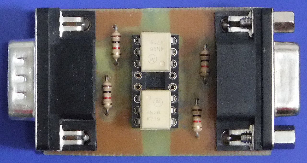
Two 4N26 (white) optocouplers are installed on a common 16-pin socket. The four 1kohm resistors and both male and female DB9 connectors are installed on the component side of the printed-circuit board:
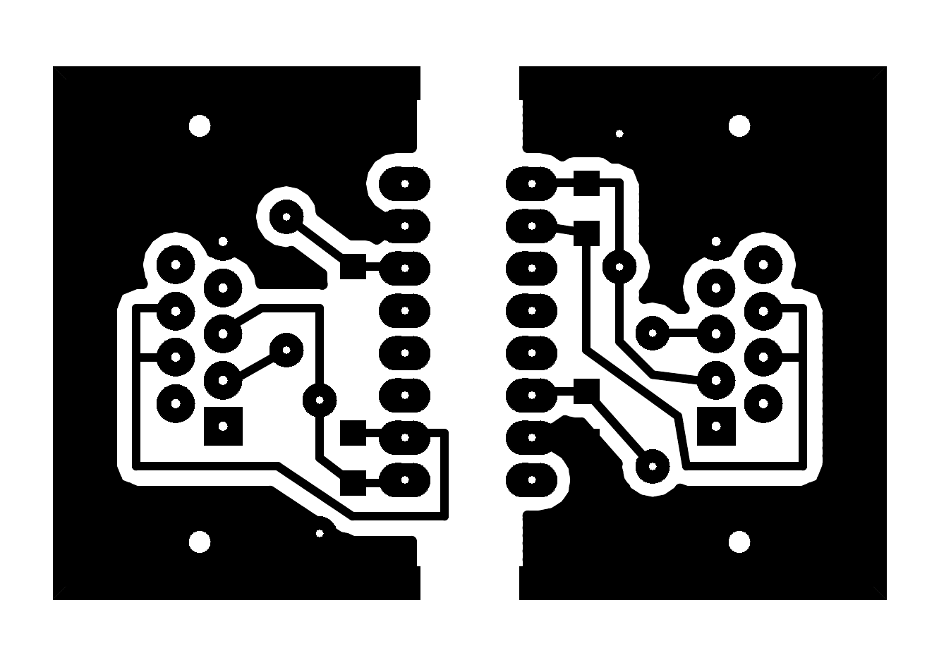
The printed-circuit board measures 50mmX32mm and is etched on a single-sided 1mm-thick FR4 laminate. The board length was intentionally selected 50mm so that the finished circuit can be wrapped in insulating "duct tape". Note that all connections including grounds are kept separated:
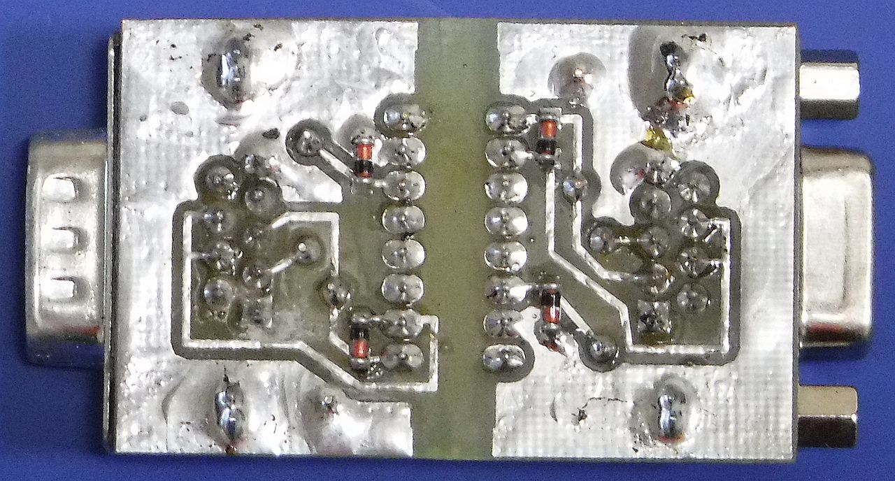
Only the four protection diodes LL4148 are installed on the bottom side. Pin 1 of both male and female DB9 connectors is marked with a square pad and is unconnected:
Similar performance was also obtained with SFH600 (black) optocouplers:
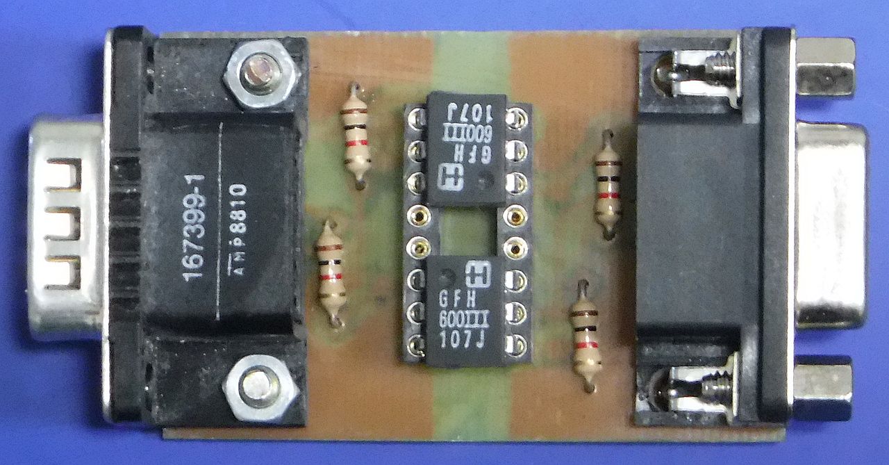
Both 4N26 and SFH600 versions of the RS232 isolator achieved similar performances with the maximum RS232 rate achieving 50kbit/s to 70kbit/s depending on component tolerances (mainly optocoupler current-transfer ratio) and port voltages over short cables. Both versions operated reliably over 20m of cable at 9600bit/s in spite of driving the RS232 ports with TTL signal levels only.