(THEORY)
(DESIGN)
(ASSEMBLY)
(OPERATION)
(ATTENUATOR)
(HOME)
DDS RF Signal Generator
Matjaz Vidmar, S53MV
5. Attenuator
Testing communication receivers requires very low signal levels in the range between -130dBm (71nVeff) and -100dBm (2.2uVeff). Since the electronics inside solid-state sources operates at signal levels between 0dBm (1mW or 0.22Veff) and +10dBm (10mW or 0.71Veff), large attenuation values and excellent shielding of the whole signal generator are required.
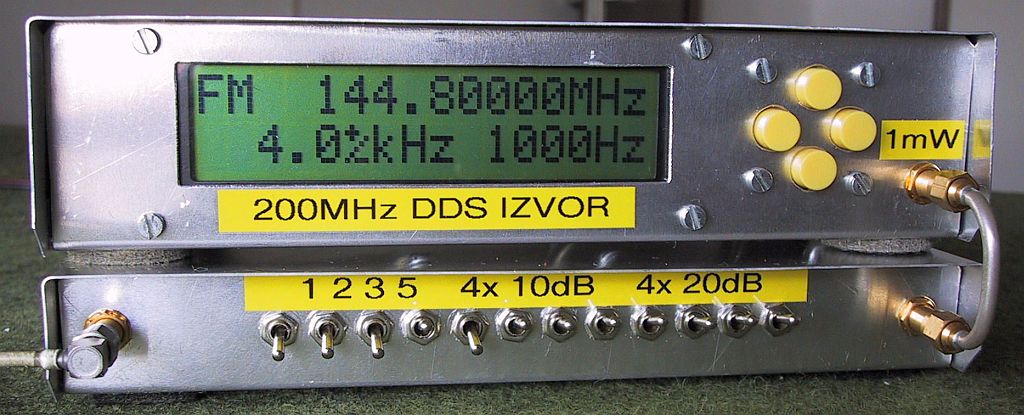
Suitable attenuators can be build in many different ways. For frequencies up to 500MHz attenuators can be built from conventional 0805 SMD resistors and simple DPDT toggle switches. An adjustable attenuator up to 131dB can be built as a chain of several stages: four 20dB stages, four 10dB stages and additional four stages for 5dB, 3dB, 2dB and 1dB as shown here:
The whole circuit of the attenuator is split into three blocks for shielding purposes. Each block contains four stages, using the same printed-circuit boards and construction techniques as in the spectrum analyzer. Each block includes four DPDT switches and two printed-circuit boards etched on 0.8mm-thick, double-sided FR4 laminate. The upper printed-circuit board is just a microstrip interconnect among the switches while the lower microstrip board also carries the SMD resistors. Each printed-circuit board measures 40x20mm. One side is not etched to act as the microstrip groundplane while the other side is shown here:
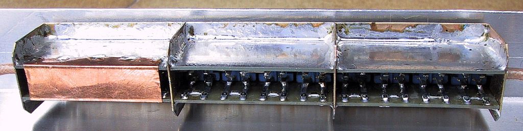
All three attenuator blocks are soldered to a single brass frame for a total of 12 switches. Input and output connections are made with double-shielded coaxial cable and good-quality SMA connectors. Ferrite beads around the input and output cables improve the shielding. The whole attenuator is installed into an aluminum box. The useful internal width is 200mm, depth 100mm and height 25mm as shown below:
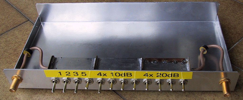
The four-times 20dB block requires additional shielding with a piece of copper foil soldered on the back of the block as shown below:
The width and depth of the aluminum box matches the box of the DDS signal generator so that both boxes can be stacked easily:
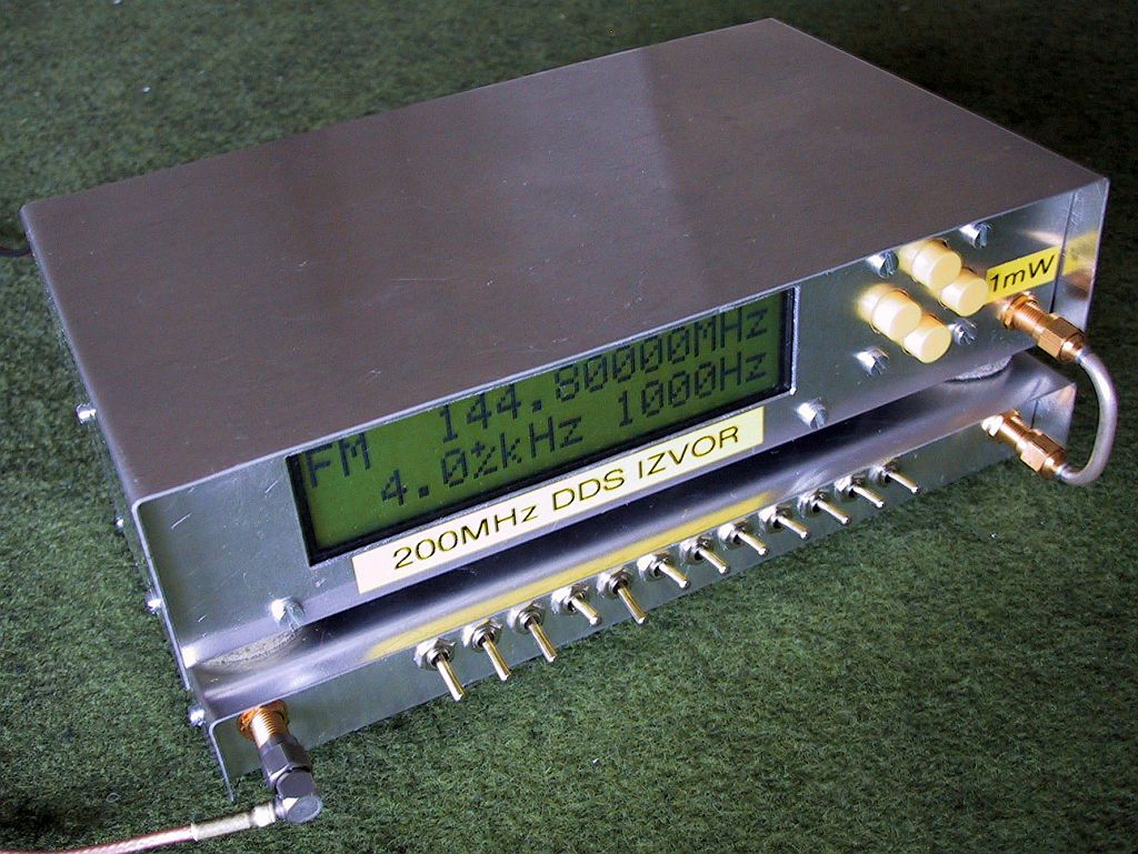
The attenuator has just two female SMA connectors. Both are installed on the front panel. The DDS signal generator is connected to the attenuator with a piece of semirigid cable with two male SMA connectors for shielding purposes:
Practical experiments have shown that the overall shielding of the DDS generator and attenuator is sufficient for testing VHF communication receivers without built-in antennas. If the VHF receiver is connected to an antenna, the unwanted signal leakage from the generator is in the one-microvolt range. Most of this spurious radiation comes from the DDS signal generator, in particular from the 12Vdc-supply cable.
(THEORY) (DESIGN) (ASSEMBLY) (OPERATION) (ATTENUATOR) (HOME)