(HISTORY)
(COUNTER)
(FRONTENDS)
(PROBES)
(ASSEMBLY)
(OPERATION)
(HOME)
Simple RF/Microwave Frequency Counter
Matjaz Vidmar, S53MV
3. Front-ends
The counter is equipped with three different front-ends. The front-ends are built as separate modules to allow an easy interchange as better components (prescalers) become available or new requirements show up.
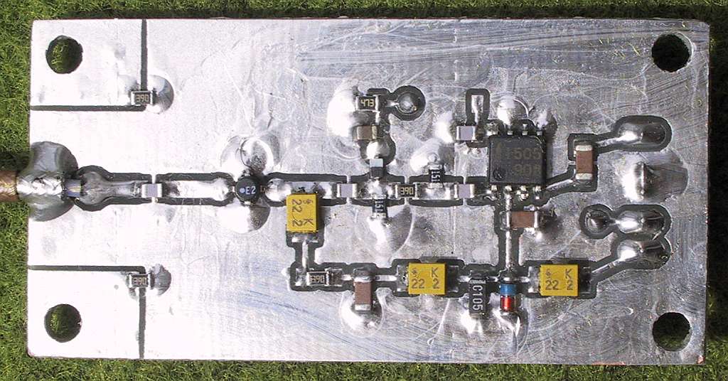
The prescaler front-end is designed around the NEC uPB1505 chip. The latter counts up to 4.9GHz and unlike the products from some other manufacturers its operation is very reliable. An ERA-2 MMIC is used to boost the input sensitivity and provide some protection for the uPB1505 at the same time. The ERA-2 can accept input-signal levels up to +15dBm (30mW). A 6dB attenuator behind the ERA-2 prevents saturating the uPB1505.
A 33kohm resistor can be used to kill the self oscillation of the uPB1505 around 2.6GHz, but this resistor also adversely affects the sensitivity and the maximum frequency of the prescaler. A BAT62-03W zero-bias schottky diode is used as a signal-level detector in the prescaler front-end. The gain of the ERA-2 sets the full scale on the bar indicator to about 0dBm.
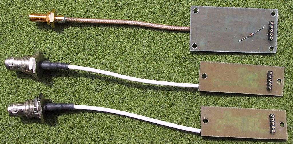
The prescaler front-end is built on a single-sided printed-circuit board measuring 30mmX60mm. The 50ohm lines are built as coplanar waveguides on a 1.6mm-thick FR4 substrate. The input cable is soldered directly to the PCB. To avoid parasitic resonances between the PCB and metal grund-plane, two additional 39ohm damping resistors are installed in series with two mounting screws.
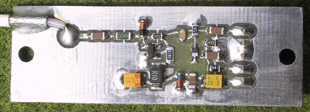
The RF front-end is designed for a high input sensitivity and low (close to 50ohm) input impedance. A high input impedance (as offered in many counters) is actually a disadvantage for RF measurements, last but no least corrupting the measurements due to low frequency (50Hz mains or switching powers supply) interference. The RF front-end includes a simple RF amplifier with a BFP196 transistor, an input protection with a 33ohm resistor and a LL4148 diode and a signal-level detector with a BAT62-03W zero-bias schottky diode.
The RF front end is built on a single-sided printed-circuit board measuring 20mmX60mm. The input cable is soldered directly to the PCB. Since the RF front-end does not include any hysteresis, it is not able to operate with sine-wave signals at very low frequencies.
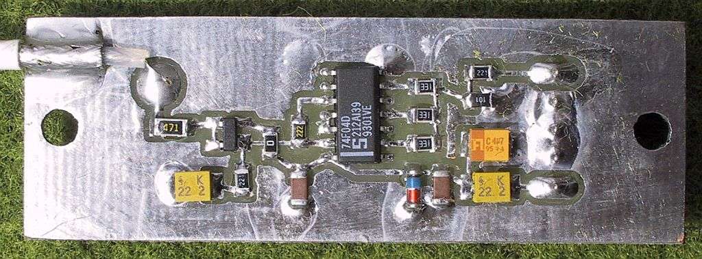
The TTL front-end is a high-impedance input. DC coupling is necessary to measure pulses with arbitrary duty cycles. Further it includes hysteresis for reliable low-frequency measurements, regardless of the waveform. The circuit includes a BF998 MOSFET source follower and a 74F04 schmitt trigger. The output of the schmitt trigger is again DC coupled to the 2N3960 in the main counter module.
The TTL front end is built on a single-sided printed-circuit board measuring 20mmX60mm. The input cable is soldered directly to the PCB. The input protection is provided by the 470ohm resistor and the zener diodes inside the BF998 (breakdown voltage between 8V and 12V). Further protection could be obtained by additional zener diodes, however the latter may include a large capacitive loading (more than 100pF).
* * * * *