I also soon faced the problem. Using a signal generator I found out that the PLL is still locked, but the sensitivity goes down by cca 50dB. I have also checked the LO leakage with a spectrum analyzer. When receiving 1400 MHz, LO is at 5614 MHz, leaking about -80dBm. In the moment when the above problem occurs, that goes down by cca 3dB, to -83dBm, but the frequency does not move a bit.
After some discussion with Adam 9A4QV, I proceeded to measure the "det1" and "det2" outputs (pins 4, 5). This has shown that the problem is in the mixer/tracking filter stage, because det1 stays and det2 falls.
The problem happens momentarily (does not look like a drift), also the frequency characteristic is a sharp cut at approx 1250MHz.
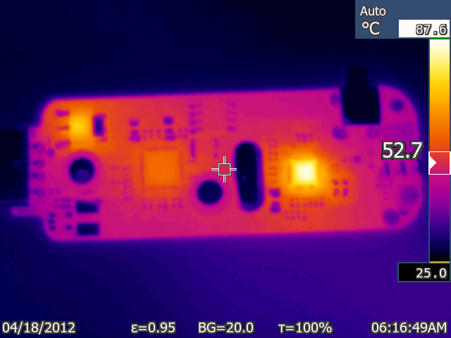
A thermal image of the dongle, ten minutes after power up, shows that the only real hot spot is the R820T, the RTL chip itself is much cooler, and the only other thing that heats up is the voltage regulator. During the 10 min warmup, a simple FFT program with 2MHz samplerate was running. The RTL chip would probably be hotter if doing its full job of MPEG decoding, but that regime is not interesting for us RTLSDR donglists.
(BTW I noticed too late that the date on the camera is off, I took the pics on 23 oct 2015)
A close up on the R820T shows a temperature over 85C:

The bottom side copper is 69C:

(NOTE: the bare metal places look cool, because of their low emissivity. Also, I am not sure about the emissivity/transparency of the solder mask, so the actual temperature of the bottom copper may be higher than indicated)
It can be seen that the bottom traces act as "thermal dams", preventing the heat from spreading across the groundplane. Observe how the right and left sides are cooler, because there are no nearby tracks, and the hot spot upper left, where the top trace comes closer, and another one approaches from the left.
The images were taken with a bare board (plastic box removed) laid on a table. When inside the plastic box, the temperatures will be even higher.
The chip should be cooling over the bottom thermal pad, but this does not seem to work very well.
Looking into the four thermal vias below the R820T (picture below, left), I could see no solder, even maybe gaps at the bottom. That is strange, as there is a solder mask free area around the vias. Looks like the through the hole components are soldered manually? I filled the vias with solder (picture below, rigt), by inserting 0.5mm solder into the vias and heating the board nearby, trying to get the solder stick to the bottom pad on the chip.
That did not bring much improvement, maybe 2 degrees on the topside, because the bottom copper plane is not capable of dissipating the heat anyway.

Seenig how hot the chip gets, one really cannot blame it for having problems above it's specified frequency range.
So, the sensible thing to do is to provide some additional cooling.
The simplest cooling system to realize is probably the use of a "thermal gap pad", as described by John Mills (external link) on rtl-sdr.com.
But the material has a rather looney price (external link) - a piece the size of the dongle board would cost more than the dongle itself! This would defeat the main advantage of the dongle - it's cheapness.
To be fair, such a big pad would be wasted - as can be seen from the bottom image, the heat can only be removed from a small area around the four thermal vias. A 1x1cm pad would be sufficient.
The thermal conductivity of the stuff above is 5 W/mK, so a 10x10mm pad of 2mm thickness would be 0.25 W/K, enough with a big margin.
But I will probably still go for a soldered solution, which also provides a good RF ground.
Usually I make small boxes from 0.5mm brass sheet, so I decided to use that for the RTLSDR also.
First, I wanted to see if just making a small "finger" would provide enough cooling.
The photos below show the process of making the cooling "finger". First, a small cut is made into the brass sheet with a jigsaw:

then it is bent upwards using small pliers:

and hammerd down over a piece of 2.5mm thick iron:

The final version looks like this:

I made the finger cca 5mm wide, although the solderable area around the thermal vias is more like 3x3mm.
Then, I applied solder to the finger, and to the via holes (as shown above). Next, the dongle is aligned over the finger and the finger heated with a soldering iron from below, until the solder between the finger and the dongle board flows.

In fact, I have laid the dongle upside down on a table, and put the brass sheet on top for soldering.
The solder blob hanging below the finger is not essential :-)
It can be seen in the new thermal image, that after ten minutes, the R820 on the top reaches only cca 54 degrees, which is more than 30 degrees cooler than before!

A picture of the whole dongle board shows that R820T is no more the hottest spot:

So, this is the solution I plan to use with the dongles. Now I must just make this into a nice brass box, which will probably include a partition for some filtering on the USB wires.