Simple "Small Signal" Harmonic Generator
with wide range output power setting
Marko Cebokli S57UUU
For RA receiver testing, sometimes you just need a small signal at a
well defined frequency, but if afield, a suitable generator is not at hand, and would be clumsy to bring.
Here I describe a very simple device to generate some harmonics in the L-band from
the transmit signal of a (small) 2m transceiver.
Once upon a time (well, a few decades ago), diode multipliers were quasi the only way for HAMs to generate signals at the higher bands. The amateur journals of that time were replete with schematics and building instructions for diode frequency multipliers. They were relatively complex, and the circuits themselves had a reputation of being tricky to get working.
This was mainly because people then wanted to get a reasonable efficiency, to produce useful (in the sense of long range radio contacts) output power.
However, when just testing receivers, the problem is usually too much of signal - so here I was intentionally trying to make a circuit with an (extremely) poor efficiency... meaning that I could use much simpler and more reliable circuits! I did not try to optimize for any particular harmonic number (multiplication ratio) - just generate as many spectral lines as possible (a.k.a. "Comb Generator"), and maybe find a nice way of attenuating them way down.
Many years ago, S53MV found out that tuner band switch diodes like
BA244 and similar, behave in a very "step recovery" like way, which makes them very good high order harmonic generators.
Of course, if you only need a very low level signal, you can try with other types of diodes. Even Schottkys, which have no reverse recovery, might give you enough of a signal for receiver testing. Just beware - they need to withstand the reverse voltage twice the peak value for your input power on 50 Ohm, for example 20V for 1W.
So, for a simple harmonic generator, I tried this simple circuit:
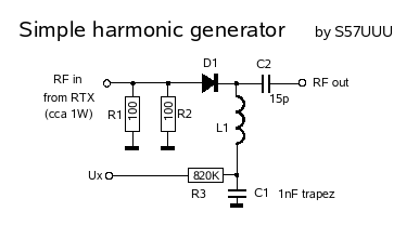
It is intended to be driven by a small, 1...2W class transceiver, something like an IC-202 or FT290. (Yeah, I'm Fred Flintstone's first cousin...)
R1 and R2 are two 1W 100 Ohm resistors, that provide a proper match to the transceiver.
D1 is the diode that does the harmonic generation.
L1 is a quasi lambda/4 air-cored choke, to provide a path to ground for DC and for the input 144MHz AC. I just took cca 4cm of 0.3mm wire, and wound it onto an 3mm drill. 4cm is less than lambda/4 for L band, but together with the parasitic inductances of the other elements, it will give a maximum of the harmonic amplitudes around 1200 MHz.
C1 is a "trapez" capacitor (leadless), for a good low inductance ground. (Do not use multilayer SMD caps - many of them are pretty bad in this respect!)
Without R3, the diode would simply pump up C1 to the input AC voltage's peak value and stop conducting, producing no harmonics.
My first idea was simply to use an potentiometer to ground for R3, to set the power of the harmonics. But then I found out, that even with a very high value for R3, like 1M, the circuit gave almost full amplitude harmonics... (going to ground with 33 kOhm only gave cca 3dB more, and with 1 kOhm, the amplitudes even went down a little)
This meant that, if I wanted adjustable power, I needed to bring an external positive DC voltage (from a separate power supply) to the Ux point. This is a bit clumsy, but it gives you a VERY wide range of power regulation, like 60 dB and more (COOOOL!!!). The lower limit is mostly set by the amount of harmonics that the transceiver produces itself. (An lowpass or bandpass filter between the RTX and the harmonic generator could improve this...)
Maybe, one could use a voltage doubling rectifier from the same input RF to generate Ux, but the harmonics produced in this rectifier could then be stronger than the desired output signal level...
If you do not need adjustable power, just ground R3.
I suggest that the first thing connected to the harmonic generator's output be a 10 or 20cm piece of coax (or longer, of course), so that the step-recovery pulse will see nice 50 ohms during it's (less than 1ns) lifetime.
I built the circuit on a piece of unetched circuit board (the material and thickness are not important, since it is simply built over the copper plane.)
It looked like this:

(in this photo, R3 is soldered to ground, for Ux=0V.)
With the above circuit, using an ITT BA244, fed from an FT290R transceiver, the output spectrums from 0.5 to 1.5GHz, for different Ux, are like this (top line reference level = +10dBm):

Ux=0V (R3 connected to ground)

Ux=12V

Ux=15V

Ux=18V

Ux=21V
The FT290 was never known to be very clean, that probably explains the sidebands...
The 144MHz fundamental is at cca -20dBm, and does not change much with Ux.
Version 2...
Well, khm, I started to make a simple device for field use, and then ended with something that needs an external power supply for signal level adjustment, HI.
Of course, it WILL operate without the external supply, it will just have a fixed output level - but the possibility of wide range output level adjustment just seemed too attractive to me, to sacrifice it.
Looking at the schematic, one can see that the external DC is consumed via an 820k resistor - obviously, the current consumption cannot be very high!!
Therefore, a battery would be a very viable solution, lasting quasi forever :-)
The problem is only, that to fully quench the diode at 1W input power, more than 20V is needed, meaning three 9V block batteries in series - again quite clumsy!
Since the DC voltage needed to quench the diode is proportional to the input AC voltage, I next tried if usable harmonics can be obtained from a lower input signal.
Going from three batteries to one meant a 3X reduction in voltage, which is about ten times less power.
After connecting the original circuit to 100mW (+20dBm) of 144 MHz from a clean lab synth, I got the following results on the 1296 MHz spectral line:
(Your mileage may vary quite a bit, depending on the diode type used etc...)

Pout = -20dBm	@  Ux = 0V
Pout = -30dBm	@  Ux = 2.63V
Pout = -30dBm	@  Ux = 3.04V
Pout = -40dBm	@  Ux = 3.22V
Pout = -50dBm	@  Ux = 3.51V
Pout = -60dBm	@  Ux = 3.89V
Pout = -70dBm	@  Ux = 4.33V
Pout = -80dBm	@  Ux = 4.93V
Pout = -90dBm	@  Ux = 5.85V
Pout = -110dBm	@  Ux = 6.81V
Pout = -120dBm	@  Ux = 7.58V
This means 100dB of adjustment ( !!!! ) with a single 9V battery - very good. This is possible because the diode is not simply used as an variable attenuator. Instead, we are influencing the very process of harmonic generation.
Since I was after a weak signal generator for RX testing, the reduction from 0dBm max output to -20dBm was no problem.
To make the circuit compatible again with the 1W 2m transceiver, I added a simple PI attenuator at the input, and connected a 9V battery with a potentiometer and an on-off switch to Ux, like this:
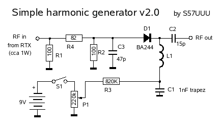
The resistor values for an 10dB 50 Ohm PI attenuator would be cca 96, 71, 96 Ohm, but
because the diode does not represent a 50 Ohm load, the attenuation was not enough.
Instead of changing the resistors, I added C3, which apart from reducing the AC voltage, also provides a nice return for the step recovery pulses, and gives a litle additional attenuation to the tranceiver's own harmonics.
If the output power of your transceiver differs, you need to suitably change the attenuator - attenuator resistor value tables are easy to find on the web. Just make sure that the resistors can handle the power (R1 and R4), and are not too inductive!
The value of the potentiometer is not critical, I just used a high valued one, to reduce current consumption from the battery. One with an on-off switch is the best for simplicity.
It would be possible to bring in Ux over a longer wire, for remote control of output power. In that case, to reduce hum and interference, a lower impedance DC voltage source, and some blocking at the harmonic generator (100nf, left side of R3...) might be needed.
One nice application of this circuit is, if you need a signal source "up in the trees" ... where you don't want to put your expensive RF synthesizer, even if you have one, and don't have the low loss microwave cable, to bring the signal up there from the ground.
In this case, this harmonic generator can be put up into the trees, and a cheaper cable used to feed it with 144MHz from the ground.
BTW, although I am writing about a 2m RTX all the time here, this circuit has no part that would be 2m specific... Any other frequency with a suitable amplitude will give you harmonics!
Higher frequencies...
As-is, the "version 2" circuit, at Ux=0V, gave me cca -40dBm at 2.4GHz and -55dBm at 3.4GHz.
"Version 1", with 1W input and R3=33 kOhm to ground gives -22dBm at 2400 and 3400, cca -40dBm at 5.7GHz and some -70dBm at 10GHz. However, as can be seen from the photo above, this circuit really was not built in "10GHz style....".
Up to SIDI debug page
Copyright info