QS1R RF input modification
1. Introduction
The QS1R is an excellent SDR receiver that covers 0-62MHz in one shot. The sampling rate is 125MHz and ADC has RF input bandwidth up to 700MHz, so one can use this receiver in other Nyquist zones beside the first one. My partucular interest is the third zone that holds 2m amateur radio frequency band (144-146MHz).
The QS1R has the ability to bypass the input LPF filter by a simple rework. Now one needs to use external antialias filters.
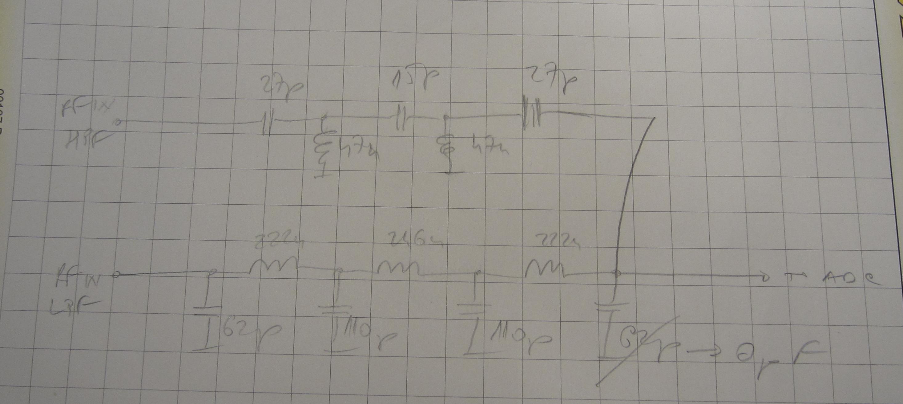
In case one wants to retain the internal LPF (HF port) AND have a dedicated VHF port, this can be achieved with a relatively simple modification. The LPF needs to be replaced with a LPF/HPF diplexer. Fortunately there is an opportunity to reuse the current LPF and PCB lines that enable LPF bypass so that the most troublesome work is drilling the hole in the front panel for additional connector (VHF port).
2. Modification
The modification is shown on pictures below.
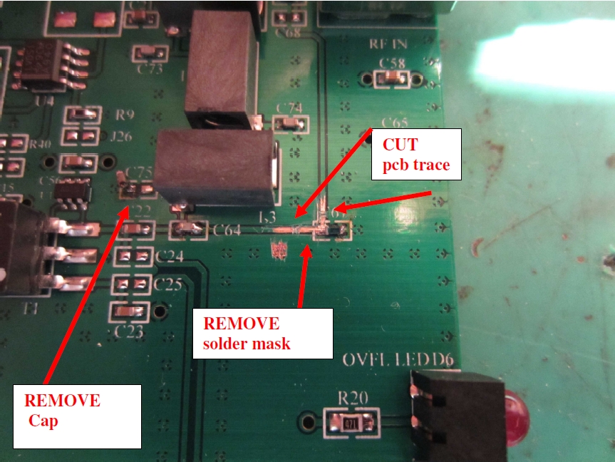
Original input LPF (with bypass components indicated):
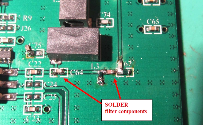
Rework step 2 (solder the rest of HPF components):
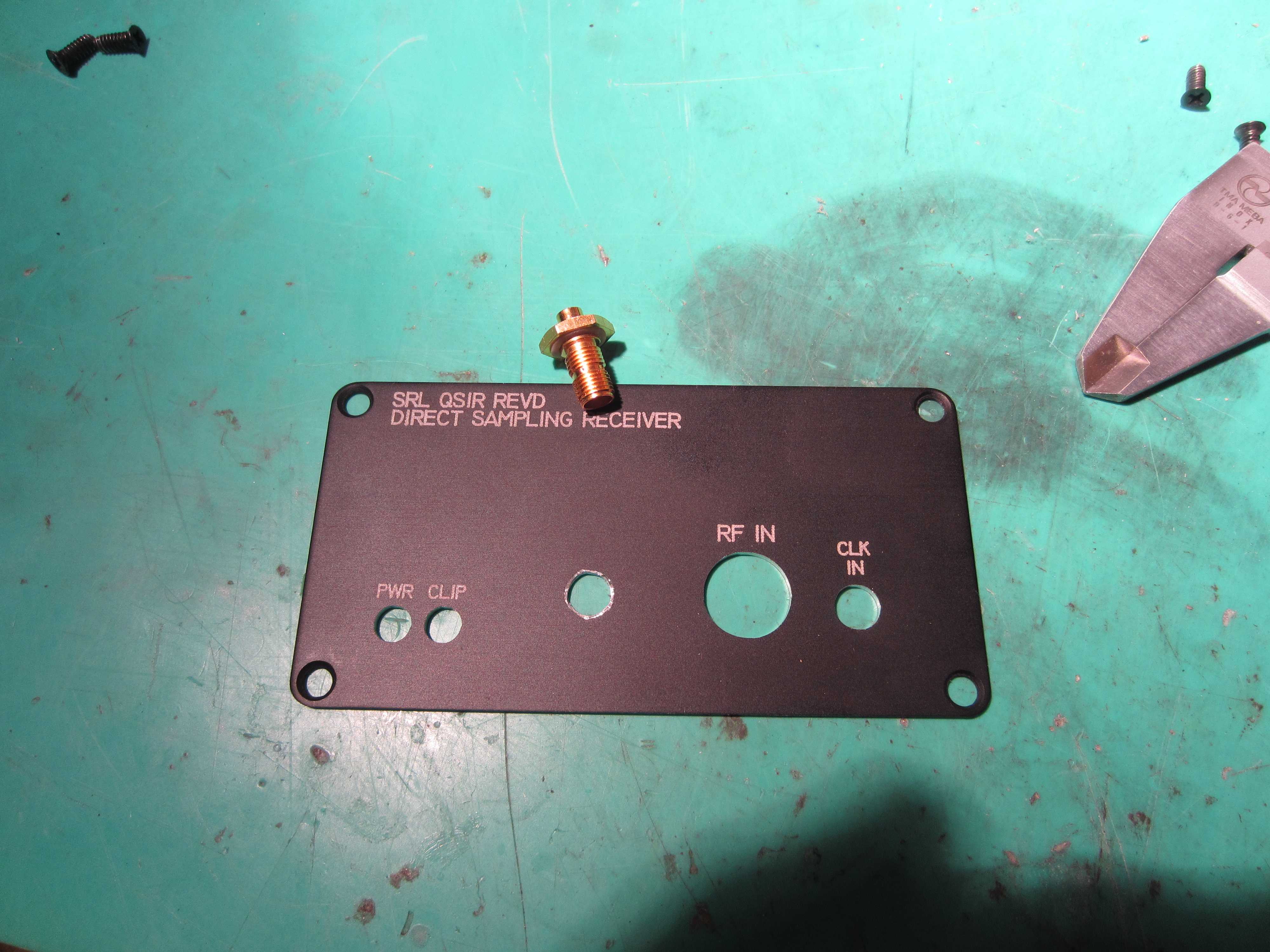
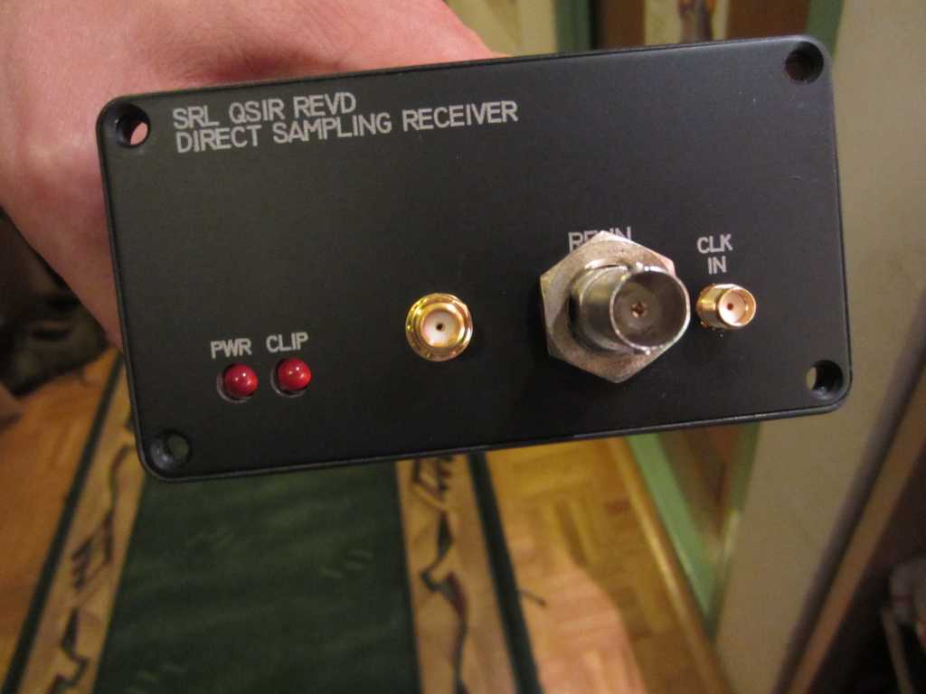
Rework step 3 (drill additional hole into front panel for your connector of choice):
Rework step 4 (make a coax connection - first remove more solder mask and cut the trace just behind the coax solder point):
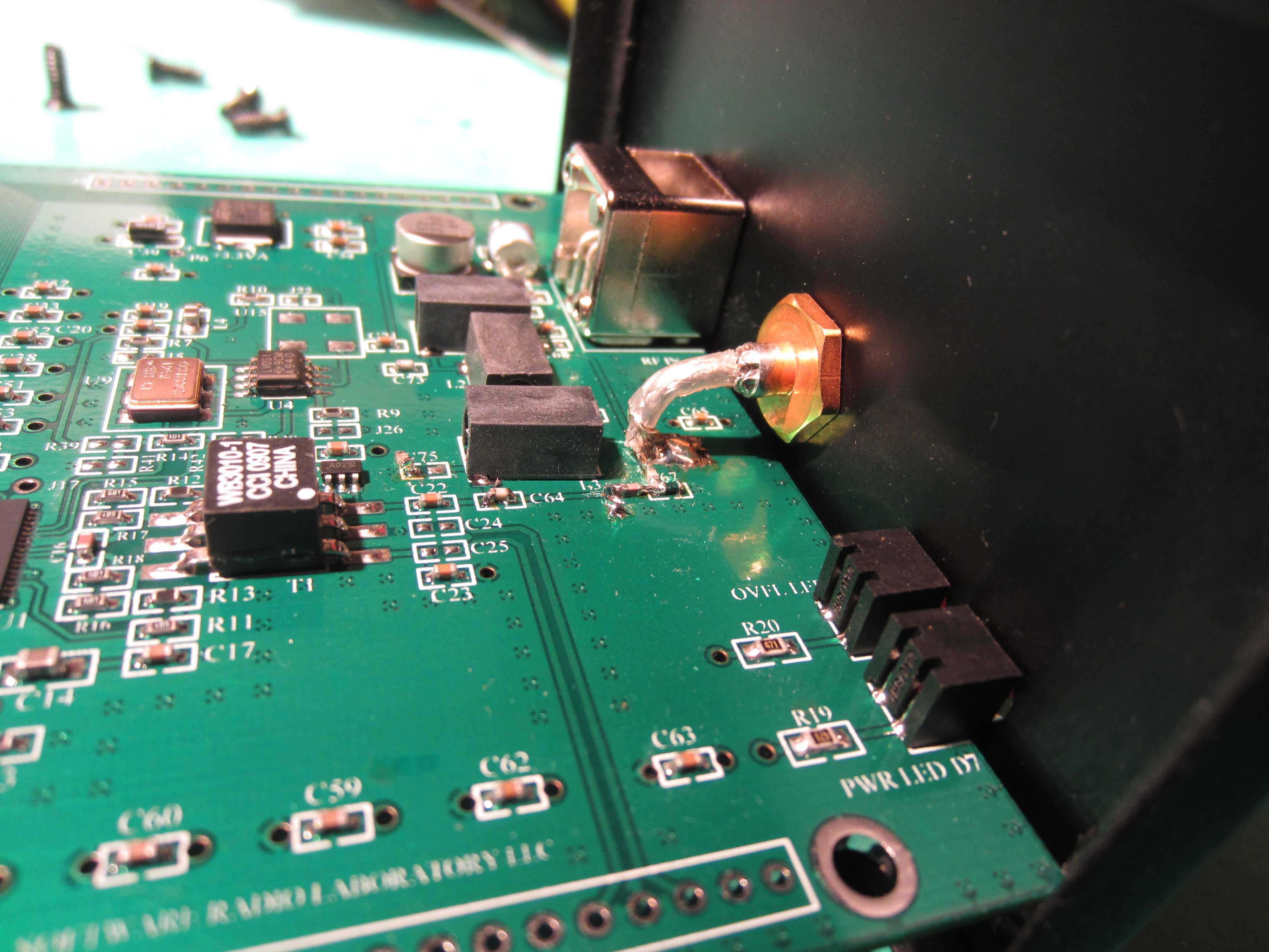
Notes:
- use 0402 or 0603 components only (if at hand use shielded 47nH inductors - as the ones in the LPF section)QS1R after modification:
As the aim was to cover 2m/70cm amateur band the secod Nyquist zone was used as a transition band for LPF/HPF filter sections. This means that this modification makes QS1R unusable for 70MHz :(
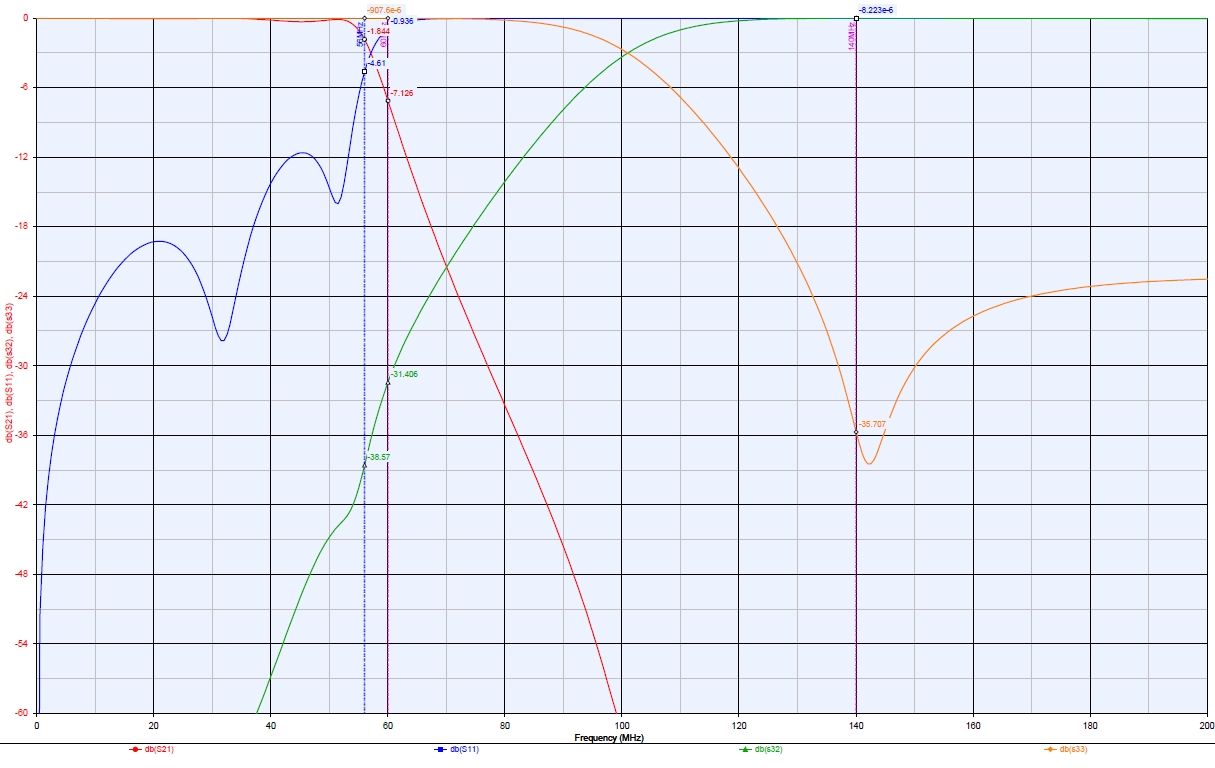
The frequency amplitude and return loss response is shown on the picture below: