Fig.5.1.1 - Double-rim SBFA.
(CAVITY)
(HORN)
(CUP)
(SBFA)
(ARCHERY)
(SELECT)
(HOME)
Weatherproof UHF & microwave cavity antennas
Matjaz Vidmar, S53MV
5. Beyond the SBFA directivity
5.1. Double-rim SBFA
The simplicity, efficiency and performance of the short-backfire antenna suggests to look for similar antenna solutions also for a cavity diameter larger than 2.5 wavelengths and directivity larger than 17dBi. Since a SBFA roughly looks similar to a parabolic dish, a possible extension is to modify the large reflector of a SBFA towards a parabolic shape. Several different solutions have been described in the literature [1].
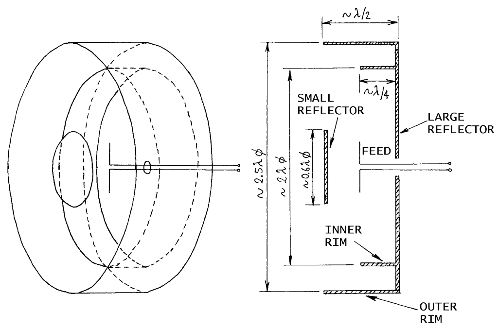
The simplest but not very efficient extension is the double-rim SBFA. The latter includes a large reflector with two concentric rims. The inner rim is just a quarter wavelength high while the outer rim is one half wavelength high as shown on the following drawing:
Fig.5.1.1 - Double-rim SBFA.
The effect of two rims is barely appreciable. A maximum directivity increase of about 1dB can be expected when compared to a conventional single-rim SBFA. As the directivity increases, the antenna becomes more sensitive to environmental conditions including the built-in radome. The following plots show the difference between two double-rim SBFAs for 13cm: one antenna without radome and the other with the aperture covered by a 1.6mm thick FR4 laminate:
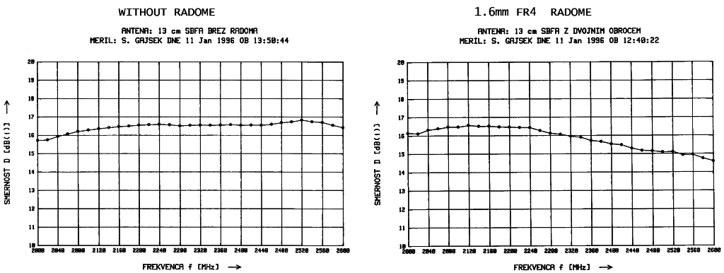
Fig.5.1.2 - Radome effect on double-rim-SBFA directivity.
As a conclusion, a double-rim SBFA without radome provides about 0.5dB more directivity than a conventional SBFA at 2360MHz. Installing a 1.6mm thick radome from FR4 laminate, the directivity drops by about 1dB and the final result is 0.5dB less directivity than a conventional SBFA. The double-rim SBFA is therefore an academic curiosity with little practical value.
A side result of all measurements is that a radome made from FR4 laminate has a considerable effect on the SBFA performance already in the 13cm band. Therefore it is recommended to reproduce the described conventional SBFA with exactly the same materials, using 0.8mm thick FR4 or slightly thicker plexi-glass for the radome.
5.2. Archery-target antenna
As the SFBA cavity becomes larger, additional circular-waveguide modes are excited. Rather than changing the shape of the large reflector, additional structures can be placed to control the amplitudes and phases of different modes. Thinking in terms of wave physics, a collimating structure in the form of Fresnel rings is required. The SBFA is already the first representative of such antennas, placing a small reflector in front of the feed dipole to control the lowest-order Fresnel zone.
A further evolution of the above theory is a collimating structure including one small-reflector disc and one annular-reflector ring. Such a structure results in a rather efficient "archery-target" antenna [3] as represented on the following drawing:
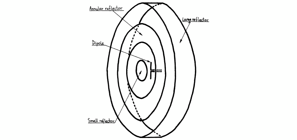
Fig.5.2.1 - Archery-target antenna structure.
The "archery-target" antenna described in this article achieves a directivity of 20.6dBi at an aperture efficiency of about 46%. The -3dB main-lobe beam-widths are about 13.8 degrees in the E plane and 10.2 degrees in the H plane. This new antenna is simple to manufacture, since the supporting structure for the small and annular reflectors can perform as a radome at the same time.
Probably the "archery-target" antenna could be further optimized. Some computer simulations suggest that both a directivity of 22dBi and better aperture efficiency could be achieved although at a reduced bandwidth. Last but not least, the structure could be extended further to include several concentric annular reflectors.
The successful "archery-target" antenna design presented in this article includes a large reflector with a diameter of about 5 wavelengths, much larger than in a typical SBFA. On the other hand, the small reflector has a diameter of 0.7 wavelengths and is comparable to the SBFA. The annular reflector extends from an inner diameter of 2.2 wavelengths to an outer diameter of 3.7 wavelengths. The reflector spacing and rim height are identical and equal to 0.7 wavelengths and this figure is also somewhat larger than in a typical SBFA:
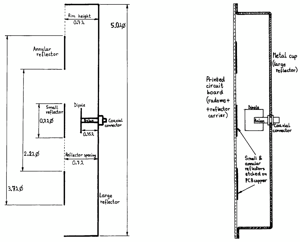
Fig.5.2.2 - Archery-target antenna design.
The prototype antenna has a large reflector diameter of 570mm, an annular reflector with an inner diameter of 252mm and an outer diameter of 420mm and a small reflector with a diameter of 80mm. The reflector spacing and rim height are set to 80mm. The small and annular reflectors are carried on a large dielectric plate: 0.8mm thick FR4 laminate with a dielectric constant of about 4.5. Although thin, this carrier plate has the effect of decreasing the optimum frequency by as much as 100MHz in the S-band frequency range.
This prototype antenna achieved the best directivity of 20.6dBi at an operating frequency of 2640MHz. The measured E-plane and H-plane radiation patterns shown on the following plots:
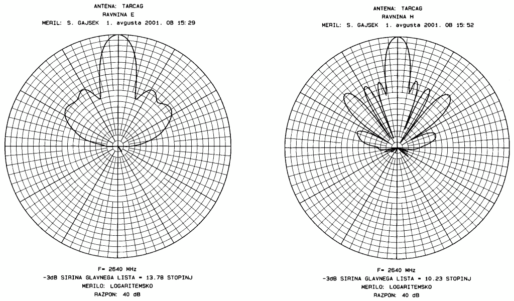
Fig.5.2.3 - E-plane and H-plane radiation patterns of the archery-target antenna.
The measured patterns in both planes at a number of different frequencies were used to compute the directivity as shown on the following plot:
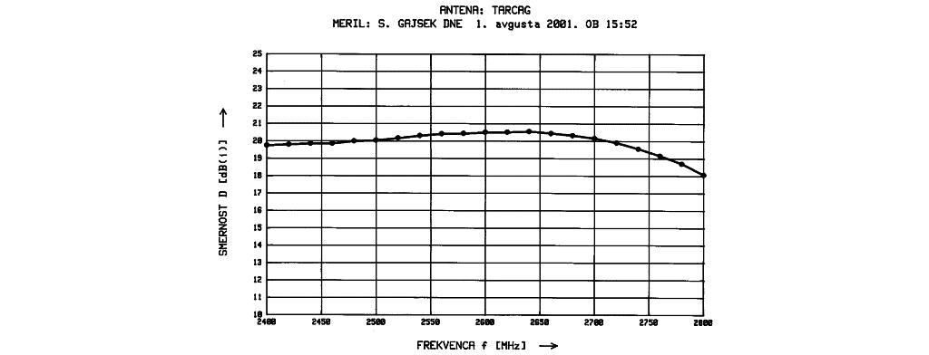
Fig.5.2.4 - Directivity of the archery-target antenna.
The first experiments with the "archery-target" antenna were made with a simple thin-wire half-wave-dipole feed. The dipole was positioned on the antenna axis of symmetry exactly half-way between the small and large reflectors just like in a SBFA. Since the thin-wire dipole had a poor impedance match to a 50-ohm source even over a narrow frequency band due to the antenna cavity loading, several other feeds were experimented.
Reasonable impedance matching (-15dB return loss over a 10% bandwidth) was obtained with a single wide-dipole feed built on a printed-circuit board as shown on the following image:
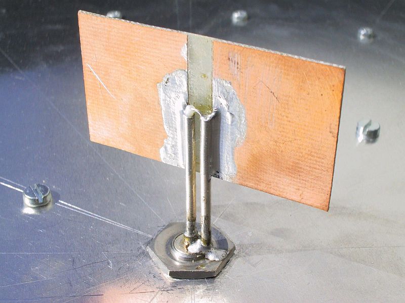
Fig.5.2.5 - Dipole feed of the archery-target antenna.
While experimenting with different feeds, small (up to +/-0.2dBi) but repeatable variations of the antenna directivity were observed as well. In particular, the directivity decreased when the wide-dipole printed-circuit board was installed parallel to the reflector plates. On the other hand, the directivity improved when the wide-dipole printed-circuit board was installed perpendicular to the reflector plates.
The feed radiation pattern can therefore contribute to a more uniform illumination of both annular apertures of the "archery-target" antenna. Effects of different feeds on other cavity antennas (cup dipoles and SBFAs) were not experimented yet.
The complete archery-target-antenna prototype is shown on the following image:
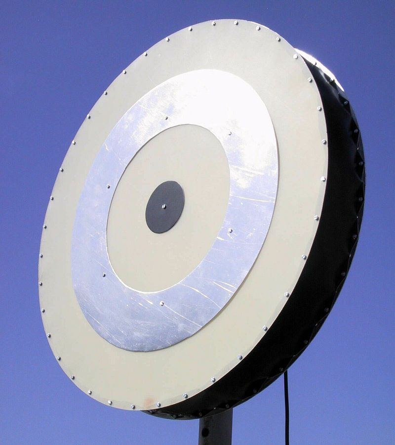
Fig.5.2.6 - Archery-target antenna prototype.