(THEORY)
(DESIGN)
(MODULES)
(ASSEMBLY)
(OPERATION)
(ARM DSP)
(HOME)
Vertical Navigation Radar
Matjaz Vidmar, S53MV
2. Design
Radio altimeters are short-range radars. Since it is difficult to generate very short pulses, short-range radars are usually built as FM-CW radars. The transmitter of a FM-CW radar sweeps its frequency according to a triangular waveform in a selected frequency range, as shown on the following illustration:
Since the received signal is delayed with respect to the transmitter, the two frequencies are not the same. In the case of a triangular sweep, the frequency difference is directly proportional to the delay and therefore to the altitude of the aircraft above the runway.
While early radio altimeters operated in different frequency bands, most aviation instruments now operate in the 4.2-4.4GHz microwave band corresponding to a wavelength of about 7cm. The required transmitter power is very low, generally below 1W. Using a 30mW transmitter at 4.3GHz, thermal noise only becomes an issue at altitudes above about 5000feet (1500m).
On the other hand, unwanted crosstalk between the transmitter and the receiver severely limits the operation of a FM-CW radar. This crosstalk represents a major noise contribution at altitudes below about 50feet (15m). FM-CW radars therefore have separate transmit and receive antennas. Although a single antenna FM-CW altimeter can be built, it will not operate at all below 50feet and its performance will be severely limited at higher altitudes.
Radio altimeters simply measure the frequency difference between the transmitter and the receiver with a frequency counter. Such altimeters can only handle one strong reflection from ground at the same time. This is sufficient to provide full assistance while landing on a large IFR airport: the reflection from a paved runway is specular providing high altitude accuracy for the flare while the whole area in front of the runway threshold is kept clear of trees and other obstacles.
A vertical navigation radar for small aircraft is required to operate in a much more complex environment with multiple reflections, like small airstrips with many obstacles and other scatterers in the neighborhood. The result provided by a simple frequency meter (like a frequency counter) is useless in this case. Since a numerical display with a single measured value for the altitude is simply insufficient to describe such a complex environment, such an instrument is considered useless by most pilots of small aircraft.
Fortunately the measurement problem is linear: in the case of multiple reflections with different delays, each reflection adds its own spectral line to the received frequency spectrum. Replacing a simple frequency meter (counter) with a spectrum analyzer for the frequency-difference (beat) signal in the receiver, multiple reflections from different targets can be processed and displayed correctly as shown on the following illustration:
A graphical display shows the delays and intensities of all reflected signals. Further, a decision circuit is required to find the altitude above ground and the latter is displayed numerically. Finally, at 500 feet (150m) or below the aircraft altitude is also announced by a voice synthesizer. The latter acts as a ground-proximity warning. It also allows the pilot to observe the runway or other instruments during the final approach and landing flare.
Certified avionics usually contains many self-test and self-calibration circuits. In some radar altimeters the latter may be even more complex than the radar itself. Yet these circuits are frequently unable to detect the most likely failures in an aircraft installation, like a damaged antenna or a broken antenna cable.
In the described vertical navigation radar, a very simple solution is proposed for the self test. Simply all available data is shown on the graphical screen, including circuit artifacts like thermal noise or antenna crosstalk. Any change in the performance of the radar or its antenna installation is immediately evident on the graphical display, making the decision whether to trust the instrument or not very simple.
The operating range of a radar should be defined first. A vertical navigation radar should work from ground: landing flare down to 0feet, up to about 5000feet above ground. Above 5000feet, the diffused reflections from many different targets in the antenna field-of-view add up to a rather inaccurate result. Pressure altimeters and GPS are orders of magnitude more accurate.
The resolution of a FM-CW radar is limited by the available RF bandwidth. Although the altimeter band extends from 4.2GHz to 4.4GHz, some safety margin has to be kept at both ends. The FM deviation is therefore limited to 150-180MHz. A straightforward calculation limits the resolution of such a FM-CW radar to about 1m (3.3feet). Dithering the triangular sweep and averaging the result improves the resolution to about 0.3m (1foot).
There are many possible choices for the triangular sweep period and corresponding beat frequency range. On the lower end, the limit is given by the Doppler shift due to the moving aircraft. On the upper end, thermal noise becomes a problem as well as sensitivity to interference from other similar radars operating at the same time in the same frequency range.
In a practical design of a vertical navigation radar, it makes sense to switch among different triangular sweep periods to optimize and simplify the beat spectrum analyzer. The block diagram of a practical vertical navigation radar is shown on the following illustration:
The beat signal processing includes two logarithmic detectors at 30kHz and 33kHz. The sweep period is switched among 32 different values. In this way, the beat signal spectrum is analyzed in 64 different points. The latter correspond to altitudes from 0feet up to 5000feet as illustrated on the following table:
The design of the beat signal processing follows the fact that most reflections are diffused. The spectrum width of a diffused reflection is about 10% of the central frequency. Therefore both the 30kHz and 33kHz filters are designed for 10% or 3kHz bandwidth. Altitude steps follow the same exponential rule, each altitude is 10% larger than the previous one. This results in a very practical logarithmic altitude scale.
A minor deviation from the described logarithmic scale can be observed at very low altitudes. This is due to the delays introduced by the electronic circuits, antenna cables and group delay of the antennas themselves. The sum of these delays totals to about 24ns corresponding to an altitude of 12feet. Of course these 12feet are subtracted from the final result in the table!
Of course the numerical values to be displayed are rounded to the nearest integer of units, tens or hundreds of feet. The voice synthesizer performs some further rounding of the measured altitudes to avoid overloading the pilot with complex messages.
The maximum Doppler shift amounts to about +/1kHz at light-plane speeds up to 120knots. Of course the final approach and landing flare are performed at much lower speeds. Further, the Doppler shift of most scatterers inside the antenna beam is much smaller than the maximum values found at the horizon. It can safely be assumed that the Doppler shift is much smaller than the 3kHz filter bandwidth. Finally, both slopes of the triangular waveform are used to cancel any influence of the Doppler shift on the measured altitude.
Although thermal noise is not an issue, the beat spectrum measurements still take some time. Low altitude measurements have to be taken more frequently than others to allow the fastest possible reaction of the pilot during the critical landing flare. One complete measurement cycle takes 400ms as shown on the following illustration:
During this 400ms period, three independent measurements are taken at low altitudes 0-40feet. Altitude data is transmitted every 133ms to the voice synthesizer and this data contains the altitude decision taken from the most recent 400ms data. Beat spectrum data is first corrected for the propagation delay that increases with distance and then the strongest return is considered the best altitude decision.
At low altitudes, the best of the last three measurements is taken. This is enough in the final approach, during the flare and during high-speed taxiing to avoid bad reflection spots (diffused reflection) and associated false messages. False alarms are however possible and can not be avoided when the aircraft stops or during really slow taxiing.
The operation of the described vertical navigation radar is illustrated on the following picture taken during a short final:
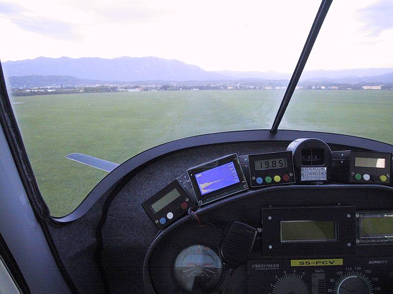
The displayed data is arranged to make best use of the available graphic LCD module WG12864B with 64 rows and 128 columns. The 64 rows are used for the 64 altitudes starting from 0feet at the bottom up to 5000feet on the top. The 128 columns are used as a logarithmic intensity scale spanning about 55dB, as shown on the following illustration:
The numerical value of the altitude is shown with large characters in the lower right corner. Smaller characters are used on the right to indicate the altitude scale. The latter includes six lines of dots corresponding to 10feet, 30feet, 100feet, 300feet, 1000feet and 3000feet. The scale is not shown on the above drawing for clarity.
The voice synthesizer receives the altitude decision as 9600bps serial data from the main processor. After the start bit, six bits 0-5 are used to indicate one of the 64 possible altitudes, bit 6 is a data-valid bit and the MSB bit 7 is always set to zero. No parity is used.
The voice synthesizer includes its own microprocessor and an analog audio-storage chip ISD2560. The latter contains several different voice messages. A voice message is only generated if a valid altitude is received from the main processor. If the same, unchanged altitude is repeated in the serial data, the voice synthesizer will wait for six seconds before repeating the same voice message. This avoids overloading the pilot by unnecessarily repeating the same message.
The proposed vertical navigation radar could be improved in many ways. An obvious improvement is the addition of a quadrature channel in the receiver. This addition effectively doubles the available RF-spectrum bandwidth from 200MHz to 400MHz resulting in a twofold improvement of the resolution. This improvement is especially important during the landing flare. Unfortunately, the addition of a quadrature channel also doubles the hardware of the receiver.
The measurement sequence could be made faster by installing more than two logarithmic detectors operating in parallel on different frequencies. An even better solution is to replace the filters and detectors with a FFT spectrum analyzer, if the latter can achieve the required 100dB dynamic range. Unfortunately, no matter how fast is the beat spectrum analyzer, there remain two bottlenecks: the elimination of bad reflection spots requires the aircraft to move and the speed of the voice synthesizer is limited too!
Finally, synthesized-aperture radar techniques could be used to upgrade the vertical navigation radar to 2D: besides looking down make it also look ahead of the aircraft. Synthesized-aperture radar requires comprehensive signal processing as well as accurate data (velocity vector) from other sources.
(THEORY) (DESIGN) (MODULES) (ASSEMBLY) (OPERATION) (ARM DSP) (HOME)