1. Modulation
Professionals and amateurs initially both used analog radio transmitters and receivers for digital communications, interfaced with suitable modems. Such a double-modulation solution is far from optimal, the radio range being compromised and the link being more sensitive to propagation distortion. Yet analog transmitters have been used for digital telemetry as high as on-board scientific satellites.
On the other hand, radio transmitters and receivers specifically designed for digital communications may be even simpler than their analog counterparts. The simplest all-digital radio link uses Bi-Phase Shift Keying (BPSK):
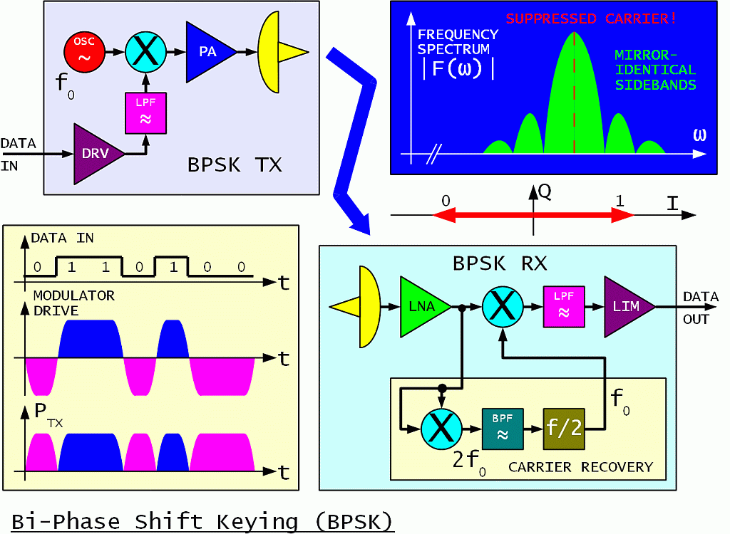
The name PSK may not be the most appropriate. Symmetrical BPSK is really a digital amplitude modulation with a suppressed carrier. Its analog equivalent is usually called DSB. Besides the phase flip, the signal power drops to zero during bit transitions. Symmetrical BPSK is therefore generated inside an analog multiplier or in other words inside a doubly-balanced mixer just like analog DSB.
The BPSK spectrum has two mirror-identical sidebands just like DSB. For rectangular drive signals the sidebands only decay slowly at about 6dB/octave. Such an unfiltered BPSK is insensitive to limiting and can be amplified by a highly-efficient class "C" RF power amplifier.
Low-pass filtering of the modulator-drive signal is usually applied to limit the BPSK sidebands. To limit the regrowth of the sidebands, a more linear RF power amplifier is required. The design of a BPSK transmitter is always a compromise between signal-spectrum width on one side and RF power amplifier complexity and efficiency on the other side.
On the other end of the radio link, the BPSK demodulator is just another analog multiplier or doubly-balanced mixer, followed by a low-pass filter to eliminate any unwanted mixing products. Analog-to-digital conversion is achieved by a simple limiting amplifier. The demodulation is coherent, since the BPSK signal is multiplied by a locally-regenerated carrier.
Carrier recovery is the most difficult task inside any coherent receiver. Yet this operation is usually not well described or not even described at all in many textbooks on telecommunications. In the case of symmetrical BPSK, carrier recovery is usually performed by yet another analog multiplier (balanced mixer) that generates the square of the input signal.
Besides doubling the frequency, the angle of any phase modulation is also doubled at the output of a squaring circuit. Symmetrical BPSK modulation 0/180 degrees therefore becomes 0/360 degrees. In other words, any phase modulation disappears leaving an unmodulated carrier at twice the frequency (2fo) at the output of the squaring circuit.
Carrier recovery therefore requires a frequency division by 2. Any frequency division, regardless of the technology used, produces an ambiguous result. Dividing by 2 produces a two-fold ambiguity. This is consistent with the definition of symmetrical BPSK: at the receiving end it is impossible to distinguish between a 0/180 phase transition and a 180/360 phase transition. The phase ambiguity of symmetrical BPSK is usually resolved by differential data encoding.
The regenerated carrier requires band-pass filtering. First, the band-pass filter acts as a flywheel to avoid losing the carrier during bit transitions. Second, the band-pass filter removes most of the noise. Both actions of the band-pass filter are required to prevent cycle slips in the frequency divider. Cycle slips disrupt the data!
As a rule of thumb, the bandwidth of the carrier BPF should be around 10% of the BPSK bit rate. A wider filter generates too many cycle slips in the frequency divider. A narrower filter increases the signal-acquisition time and the requirements for the frequency stability of both transmitter and receiver.
For example, for a BPSK bit rate of 1Mbps the filter width should be around 100kHz at 2fo. Such a communication system acquires the signal in about 10 (ten) bit times. It tolerates a frequency difference of about +/-25kHz between the transmitter and receiver or 50kHz bandwidth at fo.
If a larger frequency uncertainty of the transmitter and/or receiver is expected, the simple 2fo band-pass filter (corresponding to a first-order PLL) has to be replaced by a second-order PLL with an automatic lock search. Signal acquisition may become much longer than 1000 (one thousand) bits!
Besides the simple squaring technique for carrier recovery, a Costas loop is frequently used as a BPSK demodulator. Although the schematics of a Costas loop is much different, its performance is mathematically equivalent to the squaring technique, including the tolerance to noise and carrier-frequency offset. Although the schematics may look more complex, the Costas loop is usually simpler to implement in a Zero-IF receiver.
BPSK (or any other efficient, coherent technique) is therefore not very suitable for very low bit rates at very high carrier frequencies. Such an unfortunate solution, a very low bit rate of only 1200bps on a carrier frequency of 437MHz was flown on many amateur packet-radio satellites. Just the Doppler shift in low Earth orbit was two orders of magnitude larger than the locking range of a straightforward BPSK demodulator.
The spectrum efficiency can be doubled by combining two BPSK transmitters in quadrature to obtain Quadri-Phase Shift Keying (QPSK):
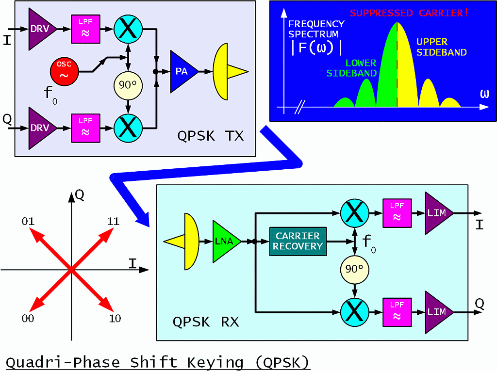
In QPSK each transmitted symbol conveys two bits of information. Although the QPSK spectrum may look similar to BPSK, the QPSK sidebands are no longer mirror images, but rather carry independent information! The analog equivalent of QPSK is called ISB or two independent LSB and USB transmissions. The QPSK spectrum-filtering and RF-power-amplifier-linearity requirements are the same as for BPSK.
A QPSK receiver contains two doubly-balanced mixers operated in quadrature as two BPSK demodulators. Crosstalk between the I and Q channels is avoided by the mathematical fact that multiplication with a carrier in quadrature does not produce any base-band signal. Of course, QPSK demodulation requires a more accurate regenerated-carrier phase than BPSK!
In order to remove any QPSK modulation for carrier recovery, the fourth harmonic of the signal has to be generated in a series connection of two squaring circuits. The bandpass operates at 4fo, followed by a frequency divider by four. The regenerated carrier has a four-fold ambiguity that has to be resolved by suitable differential encoding of both I and Q channels.
In terms of radio range, both BPSK and QPSK are equivalent: the same radio range is obtained by the same RF-power-amplifier design at the same link capacity. Both BPSK and QPSK (at an uncoded BER of 1E-6) are about 12dB below the theoretical Shannon limit for an infinite bandwidth and infinitely-complex error-correction coding.
QPSK occupies half of the bandwidth of BPSK for the same link capacity. On the other hand, QPSK is more sensitive to multipath distortion than BPSK. QPSK carrier recovery also requires a higher frequency stability than BPSK. Both BPSK and QPSK are used in a very wide range of applications, from short-range WLAN (WiFi) equipment to satellites.
The spectral efficiency can be further improved by multi-level modulations. In the case of a radio transmission it makes sense to use both different phases and amplitudes to encode different symbols. Such a modulation is usually called Quadrature Amplitude Modulation (QAM):
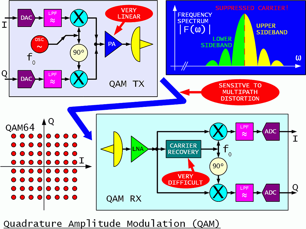
For example, each symbol of a QAM64 modulation conveys 6 bits of information or three times as much as QPSK in the same frequency band. On the other hand, QAM64 is 17dB more sensitive to noise, interference and distortion including multipath than QPSK. In the real world QAM64 is therefore limited to high-quality radio links with a wide power margin, perfect radio visibility and highly directional antennas on both ends to avoid reflections.
A QAM transmitter requires a highly-linear RF power amplifier operating in class "A". The DC-to-RF efficiency of such an amplifier is hardly above 10%. Even more difficult is the carrier recovery in the receiver. Several different techniques are possible, but none of them is fast nor simple.
A long-known technique to defeat multipath distortion is to use multi-tone modems or multi-carrier modulations. Analog multi-tone modems require lots of hardware with large filter banks. A similar and even more efficient operation to the filter banks can be performed in the digital world using the Discrete Fourier Transform (DFT). The orthogonal properties of the DFT allow an even tighter packing of the individual carriers in the frequency spectrum without crosstalk.
In a practical implementation, a string of data symbols that may range from simple BPSK to QAM64 and more is converted into an identical number of modulated carriers using an inverse DFT. The carriers are converted to analog domain using two DACs and modulate an analog QAM transmitter.
The opposite operation is performed in the receiver. The analog QAM receiver is followed by ADCs and the DFT is performed digitally to get the original symbols back. Both the DFT in the receiver and its inverse in the transmitter are performed in digital domain using the efficient FFT algorithm. Such a system is usually called Orthogonal Frequency-Division Multiplex (OFDM):
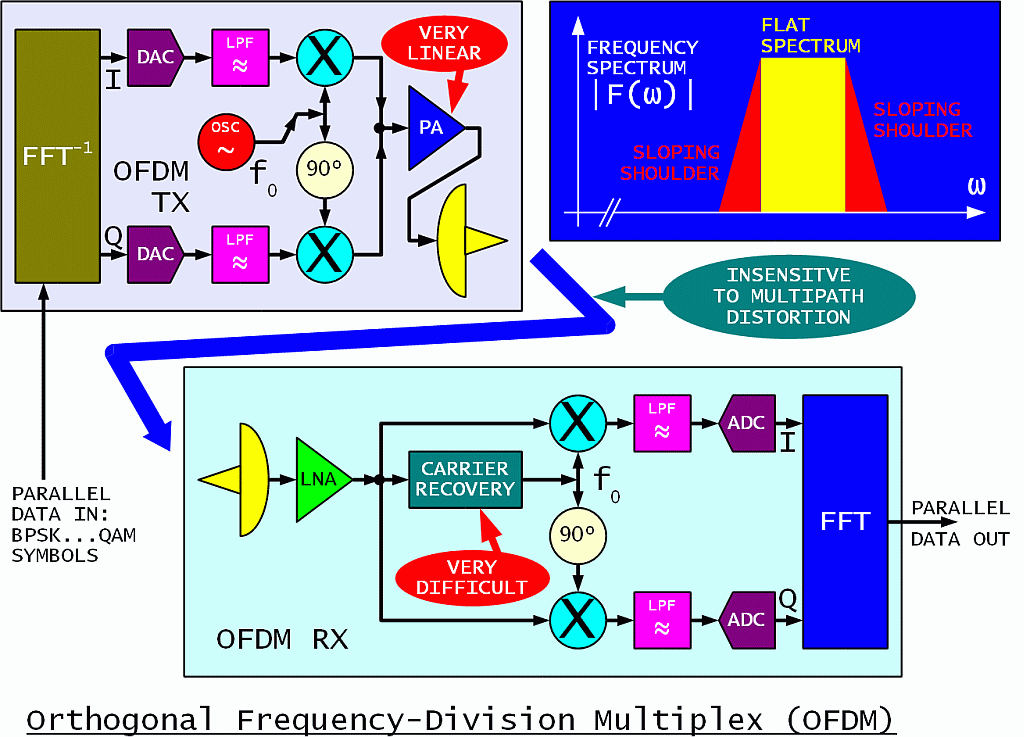
As described in textbooks written by non-engineers, OFDM looks like the ideal modulation. Due to the low data rate on the individual carriers, OFDM tolerates large multipath delays without inter-symbol interference. The shape of the frequency spectrum is almost rectangular without any additional filtering, since most of the filtering is performed inside the FFT. The analog low-pass filters in both the transmitter and receiver are only required to prevent spectrum aliasing of the sampled signals.
In the real world, OFDM has many difficult-to-comply requirements. The peak-to-average power ratio of an OFDM signal is mathematically equivalent to the number of carriers. Theoretically an OFDM system with 1000 carriers can only use 0.1% (1/1000) of the RF power generated by the transmitter! Practically some distortion may be tolerated, adding sloping shoulders to the signal spectrum and distorting the information, but improving the overall transmitter DC-to-RF efficiency to perhaps 3%.
Carrier recovery in the receiver is much more difficult than in direct systems like straightforward BPSK, QPSK or QAM. The frequency tolerance in OFDM applies to the individual carriers that are modulated at a very slow rate. For example, in a 10Mbps system with 1000 carriers, each individual carrier transfers 10kbps. The frequency tolerance for BPSK is 10% of this value or only 1kHz. In the case of QAM on individual carriers, the frequency-tolerance requirements may be tighter than 100Hz!
2. Range
Shannon's link-capacity theorem clearly states that for information transfer we both need transmitter power and spectrum bandwidth:
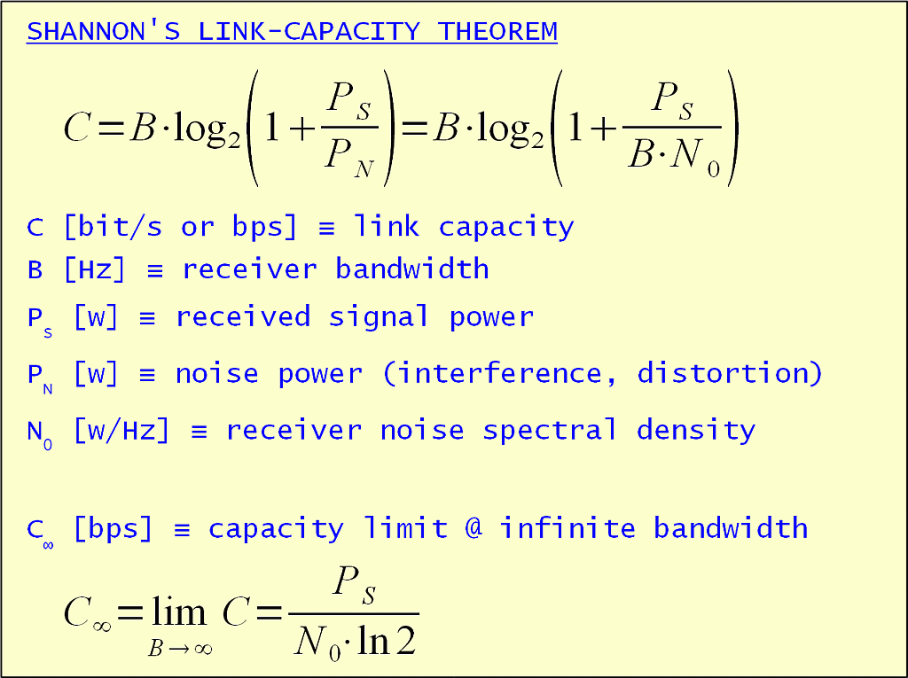
Further it is always possible to trade bandwidth for power and vice versa. Some power is always needed even in the case of infinite bandwidth. On the other hand, power requirements grow exponentially while reducing the bandwidth. Although Shannon's theorem provides a theoretical result that is difficult to approach, we can always scale the result down to the real world.
What kind of links do we need in amateur packet radio? The population density of radio amateurs is not high. We build the longest links we can afford under line-of-sight conditions. In an average hilly area this means links up to about 100km length. Their attenuation may be slightly but not considerably larger than free space.
Considering radio links in the 1Mbps range, the lower microwave radio-amateur bands of 1.3GHz, 2.3GHz, 3.4GHz and 5.7GHz should be considered. The following table shows what can be done with amateur-size antennas of 30cm (1foot) diameter:
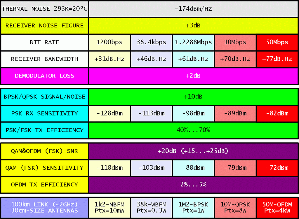
The result for the lowest speed of 1200bps is unrealistic. At these low speeds link performance was degraded by the mismatches between the radio transceiver and the modem.
The results for 38.4kbps WBFM and 1.2288Mbps BPSK are taken as a reference from many measurements on existing packet-radio links in Slovenia, including corrections for non-perfect line-of-sight conditions. At megabit speeds, transmitter power is already a limiting factor. Using BPSK or QPSK, link speeds up to about 10Mbps seem possible with reasonable transmitter powers and antenna sizes.
Complex modulations like OFDM with QAM64 modulation as used in inexpensive WLAN (WiFi) equipment on the individual carriers require lots of power. The 100km, 50Mbps link requires an average power of about 400W. At 10dB backoff as required by OFDM this means 4kW peak at the transmitter output.
Alternatively, the missing decibels could be obtained by much larger antennas. For example, 3m diameter dishes add 20dB on each link end or 40dB in total, reducing the power requirement from 4kW to just 400mW. The latter figure can be met by unmodified WLAN (WiFi) equipment.
Do we really need complex modulations like OFDM? WLAN (WiFi) equipment was designed to operate with omnidirectional antennas in a severe multipath environment. Differential delays may be much longer than the bit or symbol length causing severe inter-symbol interference:
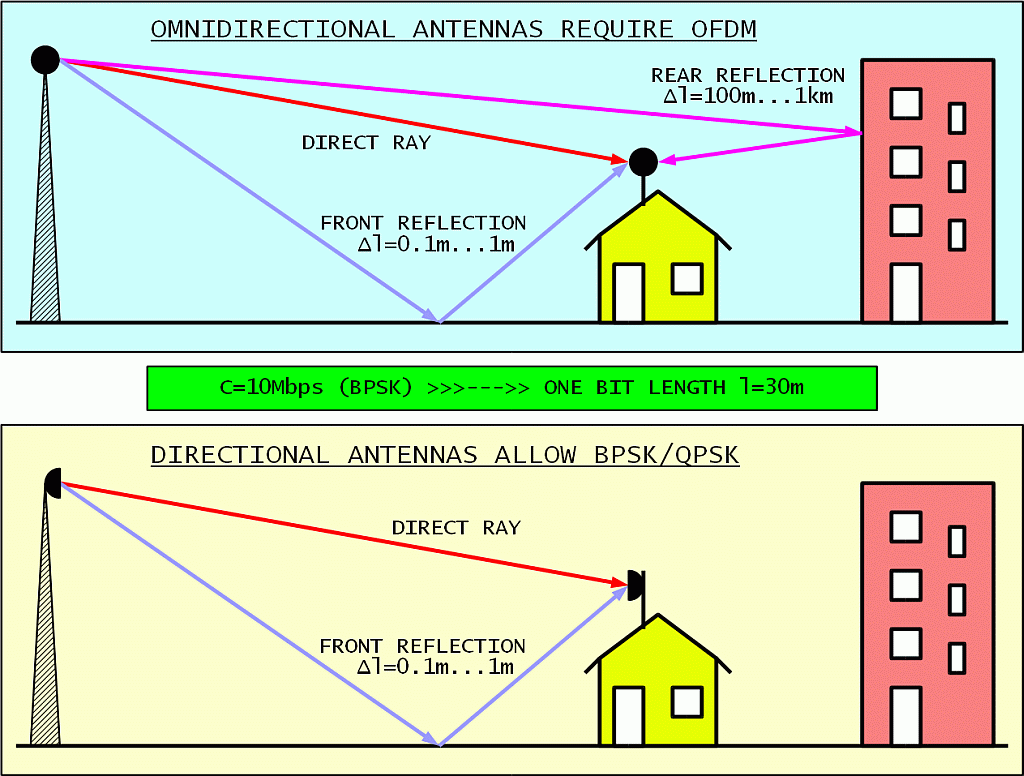
If just slightly directional antennas are used, long-delay rear reflections are eliminated. Front reflections have such a short delay that they do not cause significant signal distortion. Maybe just some increase in path loss due to destructive interference. This is a well known fact from the good old days of analog television!
Considering the range we would like to have in amateur packet radio, we need as much directivity and gain in our antennas as we can afford. Even if we use inexpensive WLAN (WiFi) equipment, we are not going to use it with omnidirectional antennas. In long links, WLAN (WiFi) equipment will switch automatically to lower transmission speeds and simpler modulations. High-level QAM over OFDM will probably never be used.
Does it still make sense to build simple homemade BPSK transceivers for packet radio or it is better to switch to inexpensive, but much more sophisticated WLAN (WiFi) equipment? The following table lists the results of our experiments:
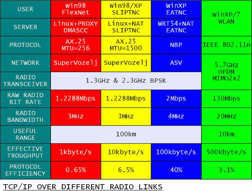
Thinking just about the radio side, the comparison is simple. WLAN (WiFi) equipment has more than ten times the capacity of homemade radios. On the other hand, homemade radios have ten times the range of WLAN (WiFi) equipment. From a network point of view it makes sense to use both, depending on the requirements of any particular link!
A much more difficult comparison is the real data throughput of each system. In the case of packet radio, bad software (Flexnet running on Win98) provided a TCP/IP throughput of only 1kbyte/s. Eliminating the bad software, the throughput raised ten-fold to 10kbyte/s. Eliminating a bad protocol (AX.25) brought another ten-fold increase of the throughput to 100kbyte/s. All this with the same, unchanged homemade BPSK transceivers!
Something similar was observed with WLAN (WiFi) equipment. The measured throughput was much lower than the advertised data rate in all experiments. WLAN (WiFi) equipment may automatically reduce the data rate in the case of a weak radio link. There may be protocol and/or implementation problems in WLAN (WiFi) too. Finally, there may be limitations of the Windows computers used in the experiment as well.
Comparing real link throughput to the occupied bandwidth, the performance of sophisticated (OFDM, MIMO) WLAN (WiFi) equipment is actually the same as that of old homebuilt BPSK transceivers supported by a good protocol (NBP). In both cases a throughput efficiency of about 25kbytes/s per 1MHz of occupied bandwidth is observed.
3. Protocol
The performance of an efficient radio link may be ruined by a bad protocol, a misused protocol or more likely several incorrectly nested protocols. The main purpose of a low-level protocol is to avoid losses in a radio link. The latter may lose information due to several reasons, the most important being noise and interference.
The lowest-level protocol should make a radio contact at least as reliable as a dedicated wire link:
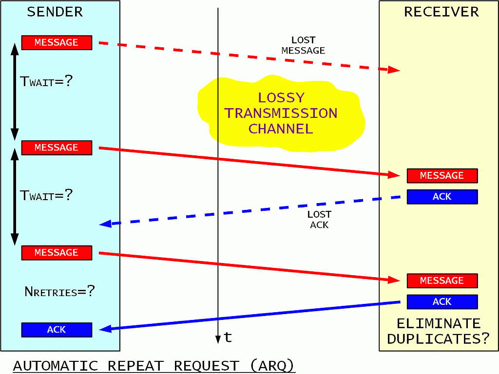
In an unreliable link the reception of each message should be acknowledged. The sender periodically repeats the message until an acknowledge is received. A maximum number of retries is specified as a safety measure, after which the unacknowledged message is discarded.
The receiver acknowledges all received messages. Since acknowledges may be lost in an unreliable link in the same way as messages, the receiver may get more than one identical copy of the same message. Such unwanted duplicates of the same message should be detected and discarded by the protocol.
In order to enable the described protocol, some additional information has to be appended to the message payload:
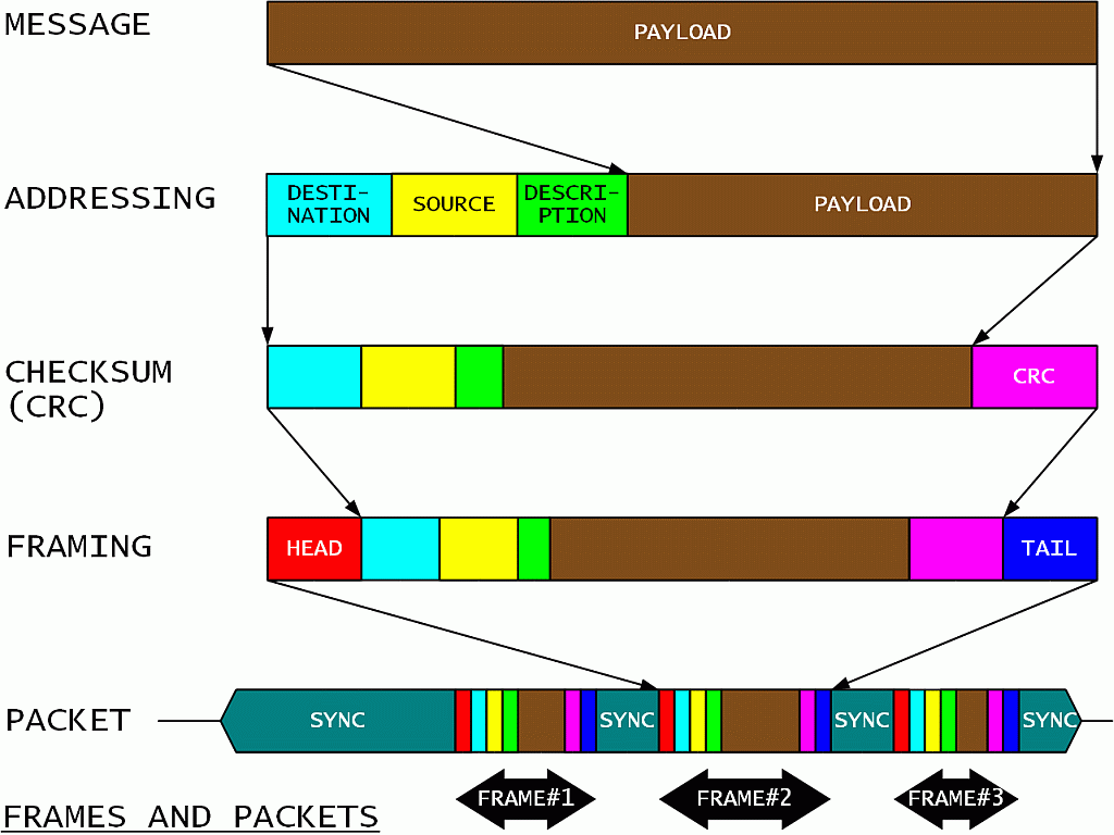
First each message payload should get a unique description field to be used by the receiver to acknowledge its reception and eliminate eventual duplicates. Second, at least source and destination addresses should be added to the data frame. There may be additional addresses specified for routing. Third, a checksum or CRC is calculated and appended to all of the above information in the data frame. Any frames with incorrect checksums are discarded by the receiver.
Next the frame is prepared for radio transmission. A head and a tail should be added to delimit the useful information of a data frame. One or more data frames are combined into a transmission packet. The latter may include a synchronization header as well as synchronization fillers in the gaps between frames and at the end of the packet. The radio transmitter is turned on at the beginning of the packet and it is turned off at the end of the packet.
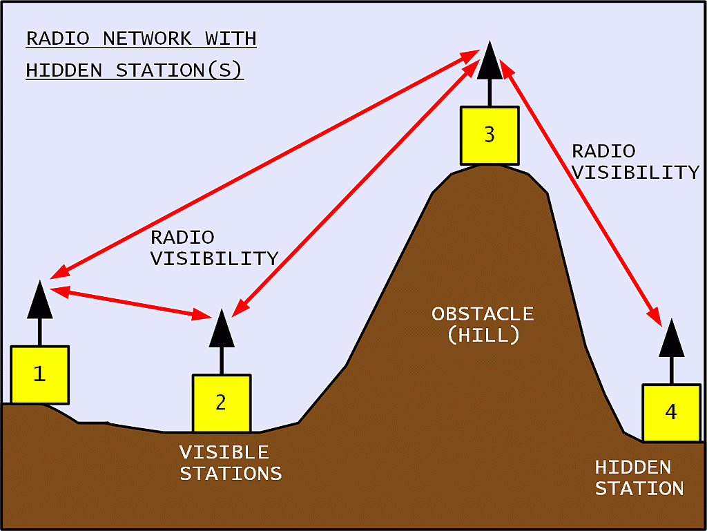
A radio network may include many participants. Direct radio links are possible between some pairs of participants. Other pairs may not have radio visibility. The latter need help from other stations to communicate. Such hidden stations may also disturb each other:
All participants share the same radio-frequency channel in a packet-radio network. In order to avoid mutual interference as much as possible, all participants listen for other transmissions. This technique is called Carrier-Sense Multiple Access (CSMA). Both random access and administered access are possible in a CSMA network:
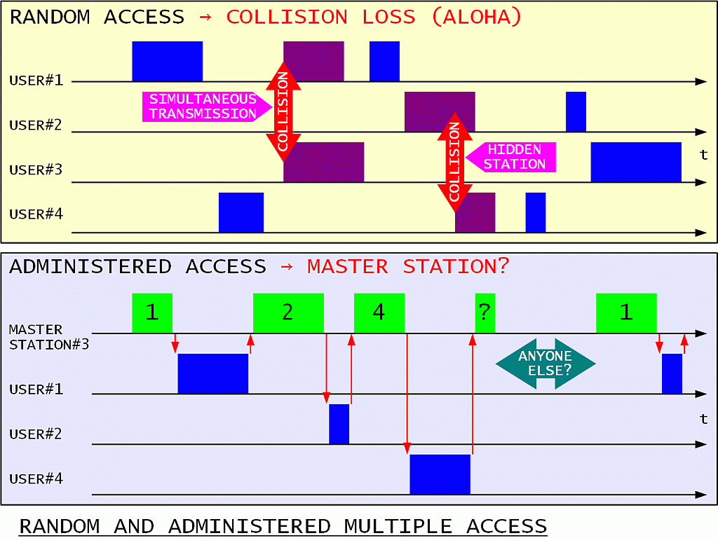
The random access loses information due to transmission collisions. Collisions may happen due to two stations starting their transmission simultaneously. Collisions may also happen due to hidden stations not knowing that someone else may already be transmitting. A good network protocol should limit the amount of collisions to avoid network collapse.
The administered access requires a master station with good radio links to all participants. The master station sequentially polls all participants. A time slot has to be reserved for random accesses of new participants. In some networks with poor radio visibility and/or complex topology a master station may not be possible nor practical. Finally, the master station may cause lots of unnecessary traffic by polling participants that have nothing to say in their time slot.
Simultaneous transmissions in a random-access network can be reduced by a careful RX/TX switching:
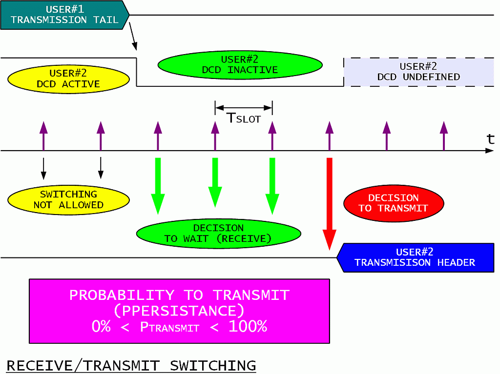
Any participant is only allowed to transmit after its Digital Carrier Detect (DCD) becomes inactive. Each participant wishing to transmit than generates a random number and compares it to the agreed probability to transmit (PPERSISTANCE). The decision may be to wait or to start transmitting immediately. If the decision is to wait, the waiting time should be larger than the sum of the turn-on delay of other transmitters, the propagation delay from other participants and the delay of the DCD.
Collisions from hidden stations can be reduced in a random access network by the RTS/CTS protocol:
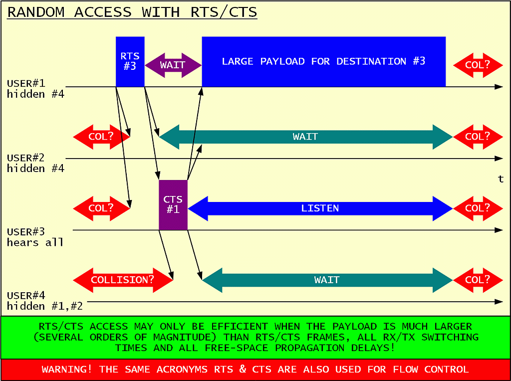
The station wishing to transmit a long message initially only sends a short Request To Send (RTS). The intended receiver answers with a short Clear To Send (CTS) acknowledge. Both RTS and CTS frames specify the amount of time all other participants are asked to wait. The long message is only transmitted after a successful RTS/CTS exchange.
Only the long message is protected from collisions in this way! The RTS/CTS frames should be as short as possible both to avoid collisions and unnecessary channel loading. The RTS/CTS protocol only makes sense when the useful message is several order of magnitudes larger than the short RTS/CTS frames and all propagation delays.
The RTS/CTS protocol may be very efficient in very-short-range WLAN (WiFi) networks inside a building. On the other hand, such a protocol is harmful, only generating unnecessary administrative traffic in long-range networks like satellite links. The propagation delays of typical links (10km...100km) in an amateur packet-radio network are large enough to make the RTS/CTS protocol useless using either commercial WLAN (WiFi) equipment or custom homebuilt BPSK radio transceivers.
Finally, even a low-level protocol should deal with congestion and flow control. A radio network may be even more complicated due to the changing performance (propagation, interference) of different radio links:
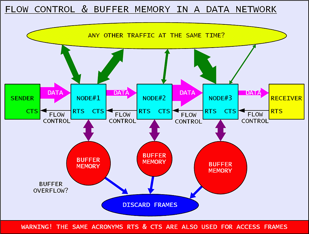
The first measure is to slow down certain links using either dedicated hardware (RTS/CTS line in a RS-232 link) or dedicated frames (RNR frames in AX.25). Next some correct frames may need to be discarded to avoid congestion. Finally, buffer overflow may always occur in spite of all of the countermeasures. Even in this case the protocol should be designed to allow a stable recovery.