(SWS)
(CIGAR)
(DESIGN)
(1G3)
(2G4)
(3G4)
(HOME)
Cigar antennas for 1.2GHz, 2.4GHz and 3.4GHz
Matjaz Vidmar, S53MV
2. Cigar antena
A slow-wave structure using resonant effects in thin metal rods has a relatively small useful bandwidth in the range of a few percent of its center frequency. The bandwidth of a slow-wave structure made from rods actually increases by increasing the diameters of the rods. In the limiting case of a wideband antenna, the metal rods evolve into (hollow) metal spheres. A simpler solution are metal disks in place of thick rods or metal spheres.
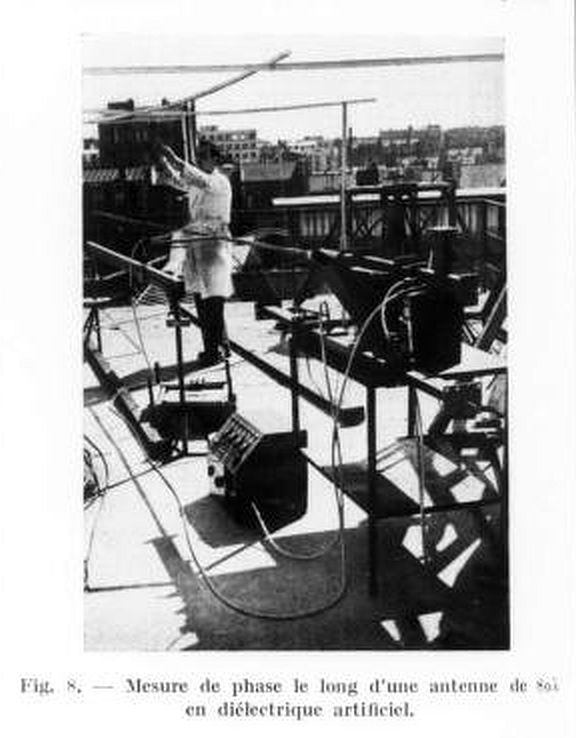
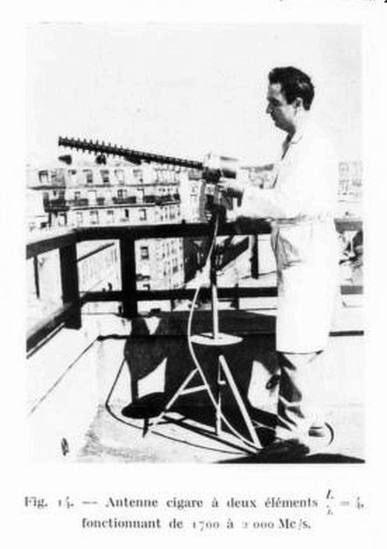
Building a slow-wave structure from metal disks was first proposed by J. C. Simon and G. Weill in: Un nouveau type d'aérien a rayonnement longitudinal (A new type of antenna for endfire radiation), Annales de Radioélectricité, vol. 8, No. 33, pp. 183-193, July 1953, Paris. The following two photos taken from the original article show the phase measurement along a slow-wave structure made from metal disks and the complete antenna for the frequency band 1.7GHz to 2GHz:
Such antennas are frequently called disk-Yagi antennas. This name is quite inappropriate since a thick metal carrier (boom) in the axis of the structure plays an important electromagnetic role, improving the directivity and bandwidth of the antenna. It therefore makes sense to use its original name "cigar antenna" as coined by its inventors.
There are several possible solutions to illuminate an artificial-dielectric lens made from metal disks on a conductive boom. The original design of a cigar antenna was fed by a waveguide horn. The simplest solution is to feed the cigar with an air-dielectric microstrip patch antenna, also called "gun antenna". A helix feed can also be used in a cigar antenna. Of course there are many other solutions to feed a cigar antenna besides those shown here:

Every antenna type has its optimum frequency range where its dimensions, size, weight and feed design are most practical for a given electrical performance. A slow-wave structure made from thin metal rods is most practical in the frequency range from 50MHz to 500MHz as originally used by Shintaro Uda. A cigar antenna is most practical at somewhat higher frequencies between 500MHz and 5GHz.
Besides its large bandwidth a cigar antenna also achieves low conductor losses due to the low current densities in the disks and thick boom. Low conductor losses allow high radiation efficiencies as well as low thermal noise added by the antenna. Low structure losses also allow very long slow-wave structures exceeding 10 wavelengths with directivities and/or gains exceeding 20dBi. As mentioned by its inventors, cigar antennas may replace "optical" antennas like parabolic mirrors in many practical applications.
All slow-wave-structure antennas require tapering of both element sizes and spacings for optimum performance. Cigar antennas can achieve non-optimum, but nevertheless quite high directivities/gains with much simpler uniform designs of identical disks at identical spacings. Typically an uniform cigar antenna still achieves a few dB more gain than a carefully tapered Yagi-Uda design of the same boom length.
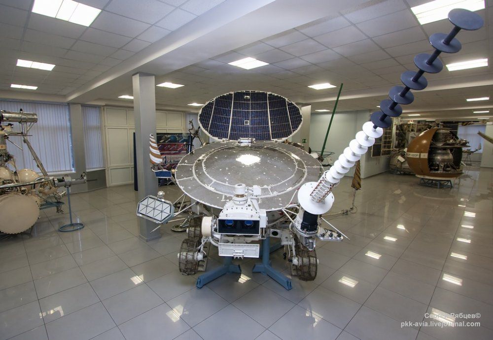
Cigar antennas are not well known. Maybe due to the original article written in French there are not many articles about cigar antennas written in English. Maybe the most famous application of cigar antennas are the video downlinks from the Soviet Lunohod Moon rovers, the first unmanned vehicles to explore another celestial body: