(SWS)
(CIGAR)
(DESIGN)
(1G3)
(2G4)
(3G4)
(HOME)
Cigar antennas for 1.2GHz, 2.4GHz and 3.4GHz
Matjaz Vidmar, S53MV
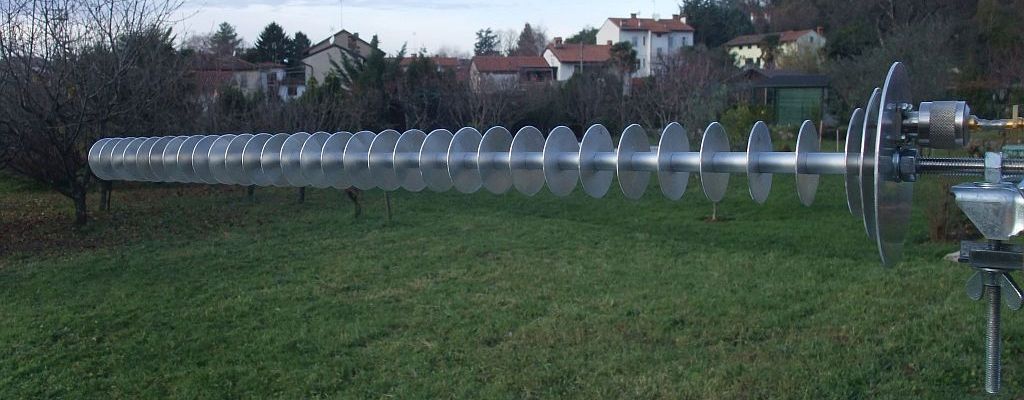
5. 33-element cigar antenna for 2.4GHz
The next experiment was to make better use of an available M8 threaded rod by increasing the number of directors of the original Russian cigar "BDM-2" at 2.4GHz. According to Günter Hoch, DL6WU, each doubling of the slow-wave-structure length should provide about 2.2dBi of directivity increase. Considering the mechanical strength of a stainless-steel M8 rod, a uniform slow-wave structure of 30 identical directors was coupled to a three-element patch feed:
The many disk elements were cut from 1mm aluminum sheet using handheld sheet-metal scissors. Spacers were made from 10mm/8mm aluminum tube. Unfortunately the latter sometimes had unacceptable tolerances. Some samples had their internal diameter less than 8mm thus not fitting on a M8 threaded rod.
Since the flange of a standard UG-58/U connector is too large for 2.4GHz, a female N connector with a smaller flange with hole spacing of just 0.5" (12.7mm) was used for the feed. The flange was attached to the reflector disk "R" with four screws M3x6mm. The center pin was soft soldered to a M3 screw using an approximately 6mm long copper tube (shield of UT141 semirigid cable). Finally the screw was attached to the driven element "S" with a M3 nut and lockwasher.
Computer simulation of a similar disk-Yagi without the boom calculated the center frequency too low by about 150MHz! This error was corrected by adding an accurate electromagnetic simulation of the boom. The corrected simulation more than doubled the number of segments in the 4NEC2 model.
Radiation-pattern measurements required a suitable reference antenna. A readily-available 30cm diameter SBFA for 2.3GHz provided a suitable bandwidth and a good forward/back ratio to suppress unwanted reflections. A dual-polarized commercial antenna with a directivity of about 10dBi eased polarization switching. Finally, when more cigar prototypes for 2.4GHz became available, they also performed as excellent reference antennas further suppressing unwanted reflections of the antenna test range.
Since radiation-pattern measurements were performed in an open field, out-of-band interference from high-power cellular-phone towers had to be suppressed by a microstrip bandpass filter 2200MHz-4000MHz in front of the diode detector. Radiation-pattern artifacts caused by interference were further suppressed by a careful choice of the lock-in frequency. For accurate results, the diode-detector response was calibrated by a precision step attenuator.
The measured radiation patterns of the final version of the 33-element cigar antenna for 2.4GHz (including unwanted reflections of the antenna test range!) are presented in the following gif animations (scanning all frequencies and both polarization planes) in both linear (field) and logarithmic (dB) scales:
The directivity was calculated from both radiation patterns in the E and H planes measured at each particular frequency in the 2100MHz-2700MHz range. At each frequency two different algorithms were used for the directivity: average of inverse partial directivities <Dj> and geometrical average of partial directivities <logDj>. The first is mathematically correct for a large number of cuts (measurement planes) of the radiation pattern while the second provides better results with just two cuts (E and H planes) for fan-beam antennas. Since cigar antennas produce rotationally-symmetrical pencil beams, both algorithms provide similar results:
The directivity of the 33-element cigar antenna for 2.4GHz was measured about 1dB higher than both a 23-element cigar for 1.3GHz and a 30cm diameter SBFA for 2.3GHz. The useful bandwidths of both the 33-element cigar and the SBFA are mainly limited by the feed bandwidth.
The impedance matching of the longer version for 2.4GHz was not particularly good. The return loss could not be found better than -10dB at any frequency (SWR worse than 1:2). Such an impedance mismatch implies an efficiency/gain loss of about -0.5dB. The feed eccentricity "e" had to be reduced from the 23mm original value down to 18mm to obtain good impedance matching to 50Ω. The suggested driven-element "S" diameter of 68mm provided the best impedance matching around 2350MHz. A smaller driven element "S" of 64mm provided the best impedance matching around 2500MHz.
Comparison tests confirmed that thanks to the excellent radiation efficiency and good impedance matching, the gain of the 33-element cigar antenna for 2.4GHz is practically identical to its directivity.